Raymarine FA-2E instruction manual Installation, Piping & Wiring, 5.1Installation

Models: FA-2E

1 23
Download 23 pages 50.34 Kb
Page 13
Image 13
5 INSTALLATION, PIPING & WIRING

3.Another technique is to install an air detection sensor in the suction port area, so that the auto valve is automatically opened by a signal sent out from the sensor and the air elimination operation is initiated.

5 INSTALLATION, PIPING & WIRING

5.1Installation

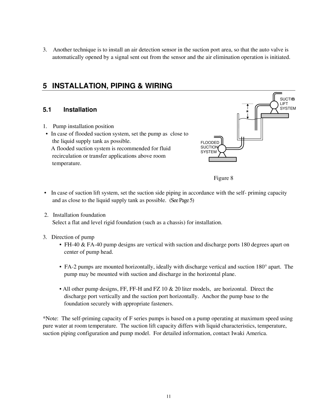
1.Pump installation position

In case of flooded suction system, set the pump as close to the liquid supply tank as possible.

A flooded suction system is recommended for fluid recirculation or transfer applications above room temperature.

*

FLOODED

SUCTION

SYSTEM

Figure 8

SUCTION LIFT SYSTEM

In case of suction lift system, set the suction side piping in accordance with the self- priming capacity and as close to the liquid supply tank as possible. (See Page 5)

2. Installation foundation

Select a flat and level rigid foundation (such as a chassis) for installation.

3.Direction of pump

FH-40 & FA-40 pump designs are vertical with suction and discharge ports 180 degrees apart on center of pump head.

FA-2 pumps are mounted horizontally, ideally with discharge vertical and suction 180° apart. The pump may be mounted with suction and discharge in the horizontal plane.

All other pump designs, FF, FF-H and FZ 10 & 20 liter models, are horizontal. Direct the discharge port vertically and the suction port horizontally. Anchor the pump base to the foundation securely with appropriate fasteners.

*Note: The self-priming capacity of F series pumps is based on a pump operating at maximum speed using pure water at room temperature. The suction lift capacity differs with liquid characteristics, temperature, suction piping configuration and pump model. For detailed information, contact Iwaki America.

11

Page 13
Image 13
Raymarine FA-2E instruction manual Installation, Piping & Wiring, 5.1Installation