4.4Liquid Circulation System Design Recommendations
In typical semiconductor wet process liquids, a catalyst such as H2O, O3 or H2O2 is added to the process
liquid. The subsequent reaction generates heat and produces extreme gassing of the liquid. Measures should be taken to reduce the amount of gas laden liquid which can enter the pump chambers. Excessive gas can cause an air lock condition for the pump which may increase the pump stroke rate to excessive levels.
For safe and efficient circulation and feeding of liquid, it is necessary to carry out air elimination and take proper safety measures.
Air elimination technique
When air enters the bellows and the pump becomes air locked, the pump stroke rate increases. If the increase is excessive, that is, higher than the specified pump stroke rate, stop the pump or carry out air elimination.
Plan A (Bubbles are blocked by means of a baffle plate)
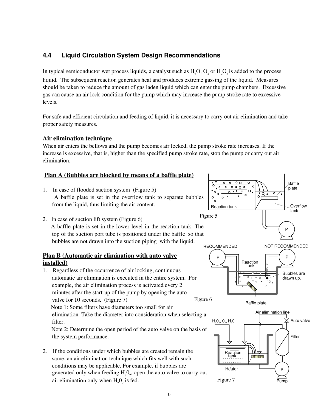
1.In case of flooded suction system (Figure 5)
A baffle plate is set in the overflow tank to separate bubbles from the liquid, thus limiting the air content.
| Baffle |
| plate |
Reaction tank | Overflow |
| tank |
2. In case of suction lift system (Figure 6)
A baffle plate is set in the lower level in the reaction tank. The | P | |
top of the suction port tube is positioned under the baffle so that | ||
| ||
bubbles are not drawn into the suction piping with the liquid. | NOT RECOMMENDED | |
RECOMMENDED |
Plan B (Automatic air elimination with auto valve |
| P | P |
installed) |
|
| Reaction |
1. Regardless of the occurrence of air locking, continuous |
|
| tank |
|
| Bubbles are | |
automatic air elimination is executed in the entire system. For |
| ||
| drawn up. | ||
example, the air elimination process is activated every 2 |
|
|
|
minutes after the | Figure 6 |
|
|
valve for 10 seconds. (Figure 7) |
| Baffle plate | |
Note 1: Some filters have diameters too small for air |
|
| |
|
| Air elimination line | |
elimination. Take the diameter into consideration when selecting a |
| ||
| Auto valve | ||
filter. |
| H202, 03, H20 | |
Note 2: Determine the open period of the auto valve on the basis of |
|
| |
the system performance. |
|
| Filter |
2.If the conditions under which bubbles are created remain the same, an air elimination technique which fits well with such conditions may be applicable. For example, if bubbles are generated only when feeding H202, open the auto valve to carry out air elimination only when H202 is fed.
10
Reaction tank
HeaterP
Figure 7 | Pump |
