Manuals
/
Raypak
/
Household Appliance
/
Boiler
Raypak
0042B, 0066B, 0180B
manual
Raypak Tube Cleaning Kit, Repairprocedures
Models:
0042B
0180B
0066B
1
29
39
39
Download
39 pages
210 b
26
27
28
29
30
31
32
33
Troubleshooting
Specifications
Install
Parts list
Vent Damper Wiring Diagram
Electrical Wiring
Warranty
Heat Exchanger Re-Assembly
Servicing Procedures
Raypak Tube Cleaning Kit
Page 29
Image 29
Page 28
Page 30
Page 29
Image 29
Page 28
Page 30
Contents
RaythermTM Type H RESIDENTIAL BOILERS Models
FOR YOUR SAFETY
0042B, 0066B,0090B 0135B, 0180B
INSTALLATION AND OPERATING INSTRUCTIONS
GENERAL SPECIFICATIONS
Contents
INSTALLATION PROCEDURES
SERVICING PROCEDURES
RECEIVING EQUIPMENT
GENERAL SPECIFICATIONS
CODE REQUIREMENTS
3. INSTALLATION PROCEDURES
MOUNTING BASE
CLEARANCEREQUIREMENTS
VENTING CONNECTIONS
COMMON VENTS
VENT DAMPER INSTALLATION
Hole in Vent Damper Blade Closed Position
FLAIR DAMPER
VENT DAMPER OPERATION
VENT DAMPER WIRING DIAGRAM
WATER CONNECTIONS & SYSTEM PIPING
GAS SUPPLY CONNECTIONS
GASPRESSURE
SINGLE-ZONEPIPING
PIPING DIAGRAMS
HOT WATER SUPPLY
ZONE HEATING WITH INDIRECT DOMESTIC
ZONE VALVES HEATINGUNITS
AIR SCOOP DIAPHRAGM EXPANSION FEED TANK VALVE
MULTIPLE ZONES WITH ZONE VALVES
MULTIPLE ZONES WITH CIRCULATORS
WIRING DIAGRAM KEY
ELECTRICAL WIRING
WIRING DIAGRAMS
Page
Page
WIRING DIAGRAM Dual-ZoneTaco Valve
WIRING DIAGRAM Single-ZoneTaco Valve
WIRING DIAGRAM Dual-ZoneHoneywell Valve
Fig. # 2228e
WIRING DIAGRAM: Power Vent System w/ Zone Valve
WIRING DIAGRAM System with 3 Zone Pumps
Fig. #2232e
Fig. #2233e Fig. #2234e
Fig. #2223.2e
WIRING DIAGRAM Primary/Secondary Pumping System
Honeywell Zone Valve
Note Low water cut-offLWCO and system switch supplied by others
GENERAL LOCATION OF CONTROLS
SERVICING PROCEDURES
For Standing Pilot Models
START-UPPROCEDURES Lighting the Boiler
Filling the System
Checking the Circulator
ROBERTSHAW PILOT
HONEYWELL PILOT
TO TURN OFF GAS TO THE BOILER Models
FOR AUTOMATIC IGNITION MODELS
TO TURN OFF GAS TO BOILER
SHUT-DOWNPROCEDURE
3.For Honeywell valve
For Robertshaw valve
FOR AUTOMATIC IGNITION SYSTEMS
SAFE SHUT-DOWNTESTS LIMIT ACTION
INSPECTION PROCEDURES BURNERS
FLAME FAILURE
INSPECTIONSCHEDULE
REPAIRPROCEDURES
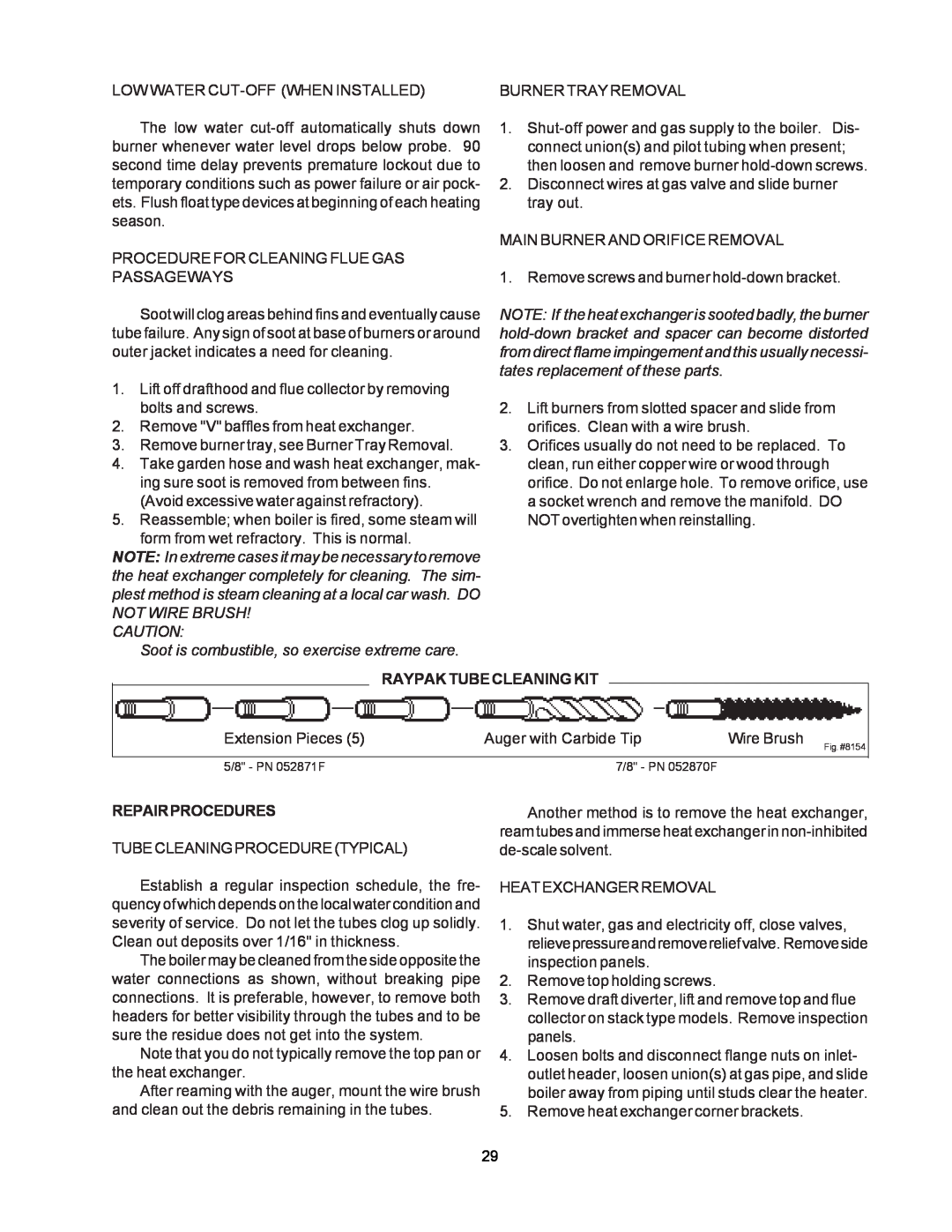
RAYPAK TUBE CLEANING KIT
HEAT EXCHANGER RE-ASSEMBLY
PROBLEM
TROUBLESHOOTING GUIDE
SOLUTIONS
IMPORTANT NOTICE
10Defective ignition module or defective gas valve
DANGER - SHOCK HAZARD
ADJUSTMENT/REPLACEMENTOF COMPONENTS
RAYPAK, INC 2151 Eastman Avenue Oxnard, CA
REPLACEMENT PARTS LIST
Page
Page
Page
HEAT EXCHANGER WARRANTY
LIMITED PARTS WARRANTY
ADDITIONAL WARRANTY EXCLUSIONS
PARTS REPLACEMENT
Top
Page
Image
Contents