NOTE: To place vent damper in the open position to
allow burner operation: Turn the power off. Turn the damper blade to fully open position (arrow facing same direction as vent pipe). Turn power on.
2.Turn the thermostat or controller up to call for heat and check that the vent damper indicator points to the open position, as shown in Fig. 11.
3.Turn the thermostat or controller down again and check that the vent damper position indicator returns to the closed position.
The vent damper must be inspected at least once a year by a trained, experienced service techni- cian. The name of the person who originally installed your vent damper is shown on the instal- lation label. Damper must be in open position when boiler main burners are operating.
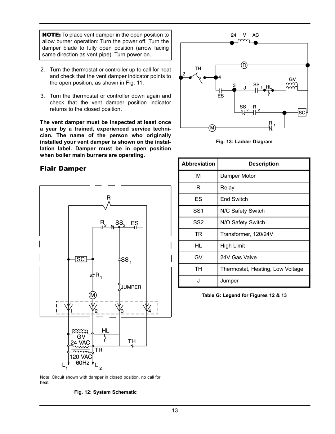
Flair Damper
R
R2 SS2 ES
| SC |
| SS 1 |
|
|
| R1 |
|
|
|
| M | JUMPER |
|
|
|
|
| |
| 1 | 2 | 3 | 4 |
| GV | HL |
|
|
|
| TH |
| |
| 24 VAC |
|
| |
| 120 VAC TR |
|
| |
L1 | 60Hz | L 2 |
|
|
Note: Circuit shown with damper in closed position, no call for heat.
| 24 | V | AC |
|
| TH | R |
|
|
2 |
|
|
| |
4 |
|
| GV | |
|
| SS 1 | ||
| 3 |
| ||
| J | HL | ||
| ES |
|
|
|
|
| SS2 | R 2 | SC |
|
|
|
| |
| M |
|
| R 1 |
|
|
|
|
Fig. 13: Ladder Diagram
AbbreviationDescription
MDamper Motor
RRelay
ES | End Switch |
SS1 | N/C Safety Switch |
SS2 | N/O Safety Switch |
TR | Transformer, 120/24V |
HL | High Limit |
GV | 24V Gas Valve |
TH | Thermostat, Heating, Low Voltage |
JJumper
Table G: Legend for Figures 12 & 13
13