Manuals
/
Raypak
/
Household Appliance
/
Boiler
Raypak
0180B, 0066B, 0042B
manual
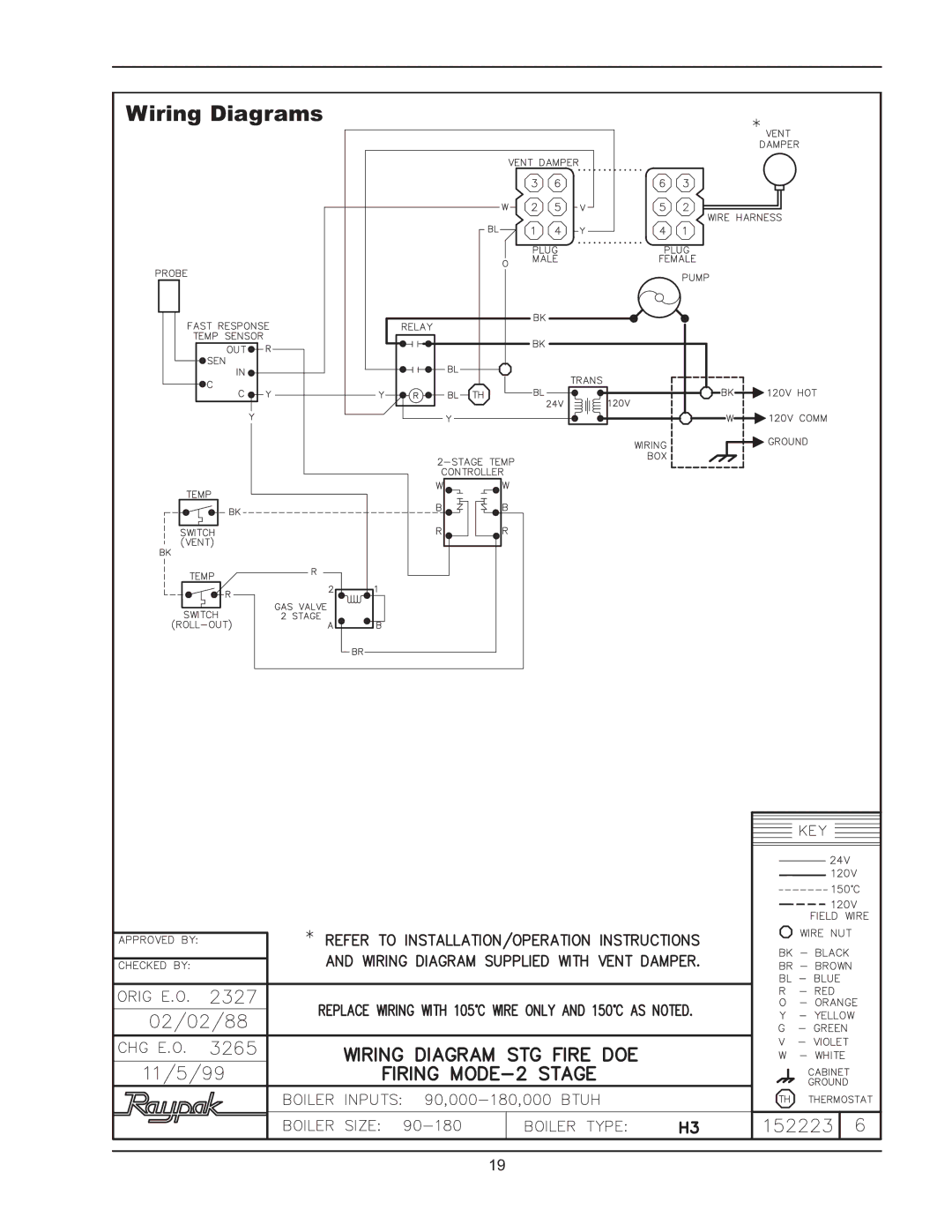
Wiring Diagrams
Models:
0042B
0180B
0066B
1
19
40
40
Download
40 pages
10.3 Kb
16
17
18
19
20
21
22
23
Troubleshooting
Specs
Install
Parts list
Piping Diagrams
Electrical Wiring
Warranty
Heat Exchanger Re-assembly
Servicing Procedures
Page 19
Image 19
Wiring Diagrams
19
Page 18
Page 20
Page 19
Image 19
Page 18
Page 20
Contents
Raytherm Residential Boilers
Page
Contents
Proposition
Pay Attention to These Terms
Receiving Equipment
General Specifications
Rating
Input Heating Net Piping Connections
Capacity
Gas NPT
Clearance Requirements
Installation
Code Requirements
Mounting Base
Model No Sq. in. of Free Area
Combustion/Ventilation Air
Model No
Venting Connections
Model No Vent Max Connector Horizontal Diameter Length ft
Roof Pitch X/12 Min. ft
Common Vents
Vent Damper Location
Vent Damper Installation Location
Vent Damper Operation
Mounting
AbbreviationDescription
Flair Damper
Vent Damper
Gas Pressure
Gas Supply Connections
Water Connections & System Piping
Model No System Flow Max. System Gpm Head ft/WC
Single-Zone Piping
Piping Diagrams
Electrical Wiring
Wiring Diagrams
Page
Page
Single-Zone Taco Valve
System with Three 3 Zone Pumps
Primary/Secondary Pumping System Honeywell Zone Valve
IID Units with Low Water Cut-off Device
Intermittent Ignition Device IID
Servicing Procedures
Sequence Operation
General Location of Controls
Filling the System
START-UP Procedures
Lighting the Boiler
For Standing Pilot Models
For Automatic Ignition Models
To Turn Off Gas to the Boiler Models 90, 135
For Honeywell valve
Shut-down Procedure
To Turn Off Gas to the Boiler
For Honeywell valve Turn gas control knob
Safe Shut-down Tests
Testing the Ignition Safety Shut-off
Burners
Inspection Procedures
Low Water Cut-Off When Installed
Procedure for Cleaning Flue Gas Passageways
Burner Tray Removal
Repair Procedures
Tube Cleaning Procedure Typical
Heat Exchanger Removal
Combustion Chamber Removal
Heat Exchanger Re-assembly
Problem Causes Solutions
Troubleshooting
Piping
Adjustment & Replacement of Components
Circulator Replacement
Replacement Parts List
Fast-Response Temperature Sensor Module Replacement
Fast-Response Temperature Sensor Probe Replacement
Limited Parts Warranty
Top
Page
Image
Contents