shipped loose. The full open position is appropriate for most systems, and ensures adequate flow through the boiler.
If system flow is inadequate, (indicated by excessive temperature drop through the system) the bypass valve can be throttled slightly. Care must be taken against
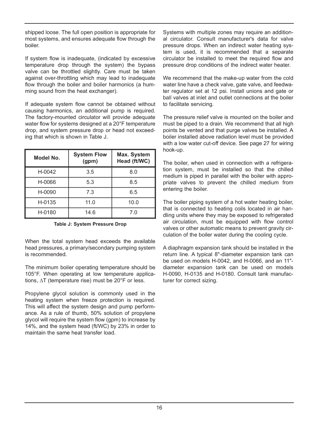
If adequate system flow cannot be obtained without causing harmonics, an additional pump is required. The
Model No. | System Flow | Max. System |
(gpm) | Head (ft/WC) | |
3.5 | 8.0 | |
5.3 | 8.5 | |
7.3 | 6.5 | |
11.0 | 10.0 | |
14.6 | 7.0 |
Table J: System Pressure Drop
When the total system head exceeds the available head pressures, a primary/secondary pumping system is recommended.
The minimum boiler operating temperature should be 105°F. When operating at low temperature applica- tions, ∆T (temperature rise) must be 20°F or less.
Propylene glycol solution is commonly used in the heating system when freeze protection is required. This will affect the system design and pump perform- ance. As a rule of thumb, 50% solution of propylene glycol will require the system flow (gpm) to increase by 14%, and the system head (ft/WC) by 23% in order to maintain the same heat transfer load.
Systems with multiple zones may require an addition- al circulator. Consult manufacturer's data for valve pressure drops. When an indirect water heating sys- tem is used, it is recommended that a separate circulator be installed to meet the required flow and pressure drop conditions of the indirect water heater. We recommend that the
The pressure relief valve is mounted on the boiler and must be piped to a drain. We recommend that all high points be vented and that purge valves be installed. A boiler installed above radiation level must be provided with a low water
The boiler, when used in connection with a refrigera- tion system, must be installed so that the chilled medium is piped in parallel with the boiler with appro- priate valves to prevent the chilled medium from entering the boiler.
The boiler piping system of a hot water heating boiler, that is connected to heating coils located in air han- dling units where they may be exposed to refrigerated air circulation, must be equipped with flow control valves or other automatic means to prevent gravity cir- culation of the boiler water during the cooling cycle.
A diaphragm expansion tank should be installed in the return line. A typical
16