Model | 1/2 in. Pipe | 3/4 in. Pipe | 1 in. Pipe | 1 1/4 in. Pipe | |||
No. | Nat. | Pro. | Nat. | Pro. | Nat. | Pro. | Nat. Pro. |
0042 | 125 | 350 | 500 |
|
|
|
|
0066 | 60 | 160 | 175 | 460 |
|
|
|
0090 | 30 | 80 | 125 | 300 | 400 |
|
|
0135 | 15 | 40 | 60 | 150 | 200 | 450 |
|
0180 |
| 20 | 35 | 90 | 115 | 300 | 425 |
Table H: Maximum Equivalent Pipe Length (Feet)
Gas Supply Connections
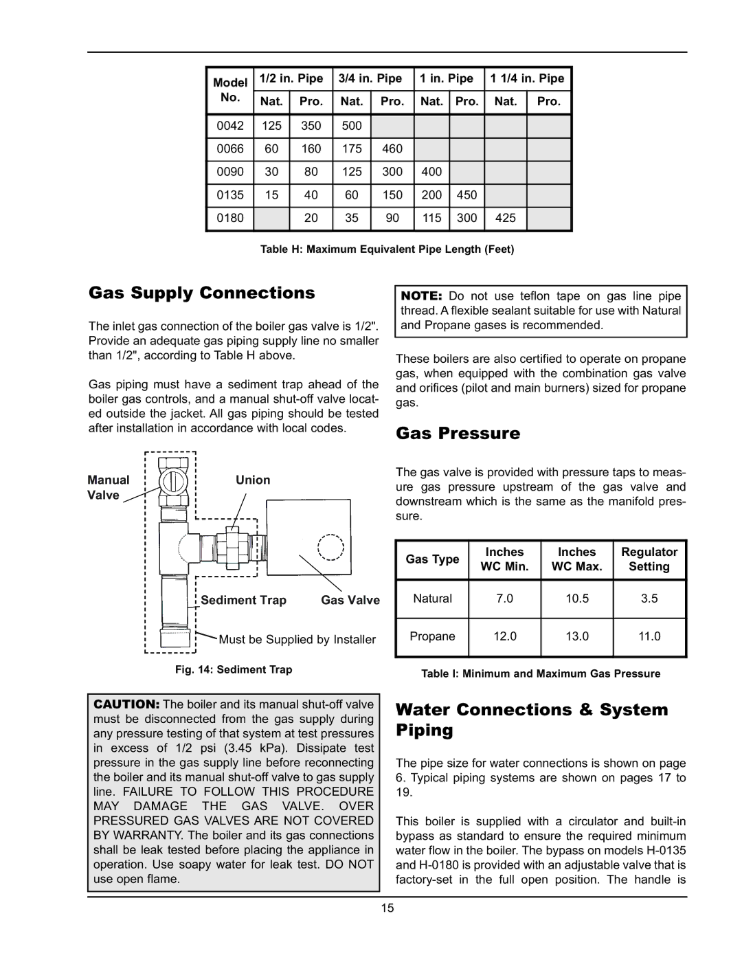
The inlet gas connection of the boiler gas valve is 1/2". Provide an adequate gas piping supply line no smaller than 1/2", according to Table H above.
Gas piping must have a sediment trap ahead of the boiler gas controls, and a manual
Manual | Union |
Valve |
|
Sediment Trap | Gas Valve |
![]() Must be Supplied by Installer
Must be Supplied by Installer
Fig. 14: Sediment Trap
NOTE: Do not use teflon tape on gas line pipe thread. A flexible sealant suitable for use with Natural and Propane gases is recommended.
These boilers are also certified to operate on propane gas, when equipped with the combination gas valve and orifices (pilot and main burners) sized for propane gas.
Gas Pressure
The gas valve is provided with pressure taps to meas- ure gas pressure upstream of the gas valve and downstream which is the same as the manifold pres- sure.
Gas Type | Inches | Inches | Regulator |
WC Min. | WC Max. | Setting | |
Natural | 7.0 | 10.5 | 3.5 |
|
|
|
|
Propane | 12.0 | 13.0 | 11.0 |
Table I: Minimum and Maximum Gas Pressure
CAUTION: The boiler and its manual
Water Connections & System Piping
The pipe size for water connections is shown on page 6. Typical piping systems are shown on pages 17 to 19.
This boiler is supplied with a circulator and
15
