INSTALLATION
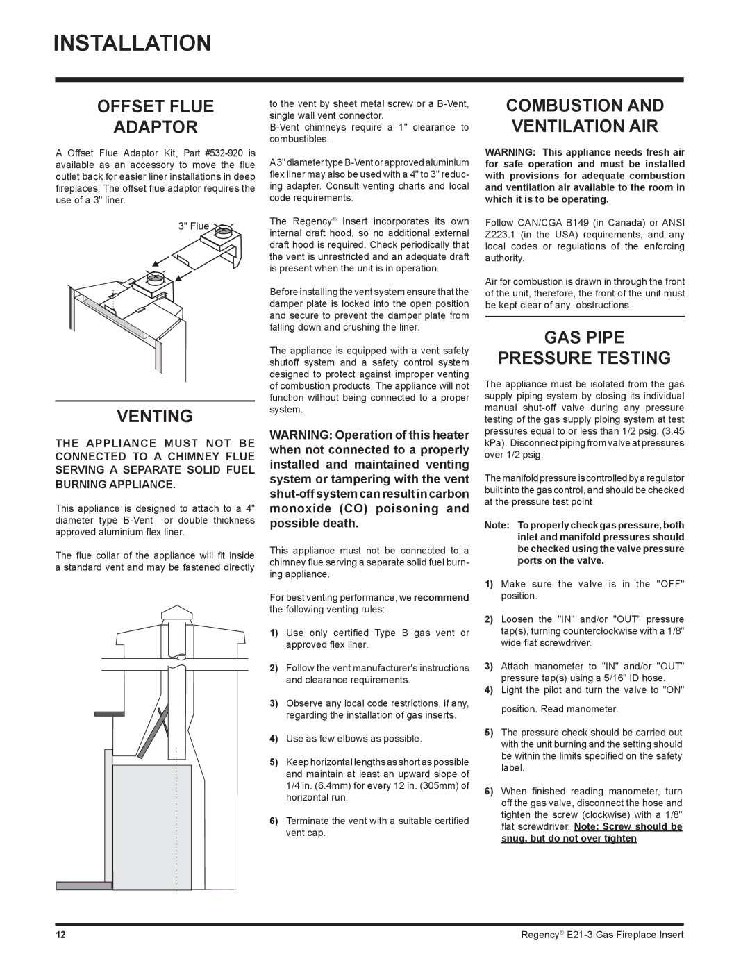
OFFSET FLUE
ADAPTOR
A Offset Flue Adaptor Kit, Part
VENTING
THE APPLIANCE MUST NOT BE CONNECTED TO A CHIMNEY FLUE SERVING A SEPARATE SOLID FUEL BURNING APPLIANCE.
This appliance is designed to attach to a 4" diameter type
The flue collar of the appliance will fit inside a standard vent and may be fastened directly
to the vent by sheet metal screw or a
A3" diameter type
The Regency® Insert incorporates its own internal draft hood, so no additional external draft hood is required. Check periodically that the vent is unrestricted and an adequate draft is present when the unit is in operation.
Before installing the vent system ensure that the damper plate is locked into the open position and secure to prevent the damper plate from falling down and crushing the liner.
The appliance is equipped with a vent safety shutoff system and a safety control system designed to protect against improper venting of combustion products. The appliance will not function without being connected to a proper system.
WARNING: Operation of this heater when not connected to a properly installed and maintained venting system or tampering with the vent
This appliance must not be connected to a chimney flue serving a separate solid fuel burn- ing appliance.
For best venting performance, we recommend the following venting rules:
1)Use only certified Type B gas vent or approved flex liner.
2)Follow the vent manufacturer's instructions and clearance requirements.
3)Observe any local code restrictions, if any, regarding the installation of gas inserts.
4)Use as few elbows as possible.
5)Keep horizontal lengths as short as possible and maintain at least an upward slope of 1/4 in. (6.4mm) for every 12 in. (305mm) of horizontal run.
6)Terminate the vent with a suitable certified vent cap.
COMBUSTION AND VENTILATION AIR
WARNING: This appliance needs fresh air for safe operation and must be installed with provisions for adequate combustion and ventilation air available to the room in which it is to be operating.
Follow CAN/CGA B149 (in Canada) or ANSI Z223.1 (in the USA) requirements, and any local codes or regulations of the enforcing authority.
Air for combustion is drawn in through the front of the unit, therefore, the front of the unit must be kept clear of any obstructions.
GAS PIPE
PRESSURE TESTING
The appliance must be isolated from the gas supply piping system by closing its individual manual
The manifold pressure is controlled by a regulator built into the gas control, and should be checked at the pressure test point.
Note: To properly check gas pressure, both inlet and manifold pressures should be checked using the valve pressure ports on the valve.
1)Make sure the valve is in the "OFF" position.
2)Loosen the "IN" and/or "OUT" pressure tap(s), turning counterclockwise with a 1/8" wide flat screwdriver.
3)Attach manometer to "IN" and/or "OUT" pressure tap(s) using a 5/16" ID hose.
4)Light the pilot and turn the valve to "ON" position. Read manometer.
5)The pressure check should be carried out with the unit burning and the setting should be within the limits specified on the safety label.
6)When finished reading manometer, turn off the gas valve, disconnect the hose and tighten the screw (clockwise) with a 1/8" flat screwdriver. Note: Screw should be snug, but do not over tighten
12 | Regency® |