INSTALLATION
|
| |
45 | ||
B)02- |
|
|
| Side View |
|
| Bracket | Front edge of |
|
| rear burner |
The bottom right edge of Log
9)Place Front Left Log
G)02-44
10)Place the embers and Rockwool on the exposed front burner tray.
11)Test fi re to ensure proper light off (make sure fl ame fl ows smoothly from one end of burner to the other. If there is any fl ame hesitation, check that area for any blockage of the burner port.
12)Install fl ush glass and optional bay glass as per instructions in this manual.
|
|
| F)02- | |
|
|
| 48 |
|
| 47 |
|
| |
|
| - |
|
|
D)02 | E)02 |
| ||
|
|
| ||
REGENCY FACEPLATE
&TRIM
INSTALLATION
1)Lay the faceplate panels fl at, face down on something soft so they don't scratch.
2)Take the top faceplate and align the holes in it with the holes in the side panels. Using the screws provided, attach from the top of the panel (the holes in the top panel are slightly larger than the holes in the side panel
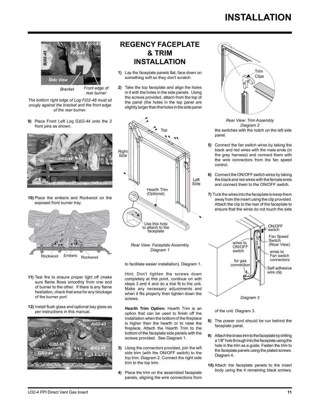
Rear View: Faceplate Assembly
Diagram 1
to facilitate easier installation). Diagram 1.
Hint: Don't tighten the screws down completely at this point, continue on with steps 3 and 4 and do a trial fi t to the unit. Make any necessary adjustments and when it fi ts properly then tighten down the screws.
Hearth Trim Option: Hearth Trim is an option that can be used to fi nish off the installation when the bottom of the fi replace is higher than the hearth or to raise the
fi replace. Attach the Hearth Trim to the bottom of the faceplate side panels with the screws provided. See Diagram 1.
3)Using the connectors provided, join the left side trim (with the ON/OFF switch) to the top trim. Diagram 2. Connect the right side trim to the top trim.
4)Place the trim on the assembled faceplate panels, aligning the wire connections from
Rear View: Trim Assembly
Diagram 2
the switches with the notch on the left side panel.
5)Connect the fan switch wires by taking the black and red wires with the male ends (in the grey harness) and connect them with the wire connectors from the fan speed control.
6)Connect the ON/OFF switch wires by taking the black and red wires with the female ends and connect them to the ON/OFF switch.
7)Tuck the wires into the faceplate to keep them away from the insert using the clip provided. Attach the clip to the rear of the faceplate to ensure that the wires do not touch the side
Diagram 3
of the unit. Diagram 3.
8)The power cord should be run behind the faceplate panel.
9)Attachthebrasstrimtothefaceplatebydrilling a1/8"holethroughintothefaceplateusingthe hole in the trim as a guide. Fasten the trim to the faceplate panels using the plated screws. Diagram 4.
10)Attach the faceplate panels to the insert body using the 4 remaining black screws.
11 |