INSTALLATION
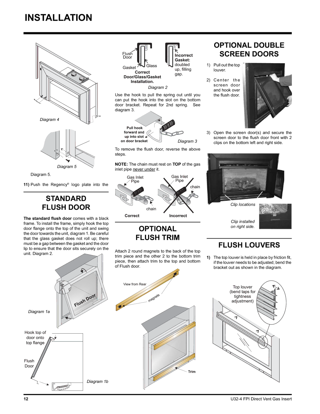
Diagram 2
Use the hook to pull the spring out until you can put the hook into the slot on the bottom door bracket. Repeat for 2nd spring. See diagram 3.
Diagram 4
OPTIONAL DOUBLE
SCREEN DOORS
1)Pull out the top louver.
2)Center the screen door and hook over the fl ush door.
Diagram 5
Diagram 5.
11)Push the Regency® logo plate into the
STANDARD
FLUSH DOOR
The standard flush door comes with a black frame. To install the frame, simply hook the top door fl ange onto the top of the unit and swing the door towards the unit, diagram 1. Be careful that the glass gasket does not roll up; there must be a gap between the gasket and the door lip to ensure that the door sits securely on the unit. Diagram 2.
Diagram 1a
Diagram 1b
Diagram 3
To remove the fl ush door, reverse the above steps.
NOTE: The chain must rest on TOP of the gas inlet pipe never under it.
OPTIONAL
FLUSH TRIM
Attach 2 round magnets to the back of the top trim piece and the other 2 to the bottom trim piece, then attach trim to the top and bottom of Flush door.
3)Open the screen door(s) and secure the screen door to the fl ush door front with 2 clips on the bottom left and right side.
Clip locations
Clip installed on right side.
FLUSH LOUVERS
1)The top louver is held in place by friction fi t, if the louver needs to be adjusted; bend the bracket out as shown in the diagram.
12 |