INSTALLATION
cord is hooked up to the fan switch and blower. Plug 3 wire cord into a suitable receptacle. Do not cut the ground terminal off under any
CLEARANCES
circumstances.
When connected with 120 volts, the appliance must be electrically grounded in accordance with local codes, with a current version of CSA C22.1 (in Canada) or in the absence of local codes, with the National Electrical Code ANSI/ NFPA
Note: This unit is equipped with a heat sensor thermodisc which will prevent the blower from operat-
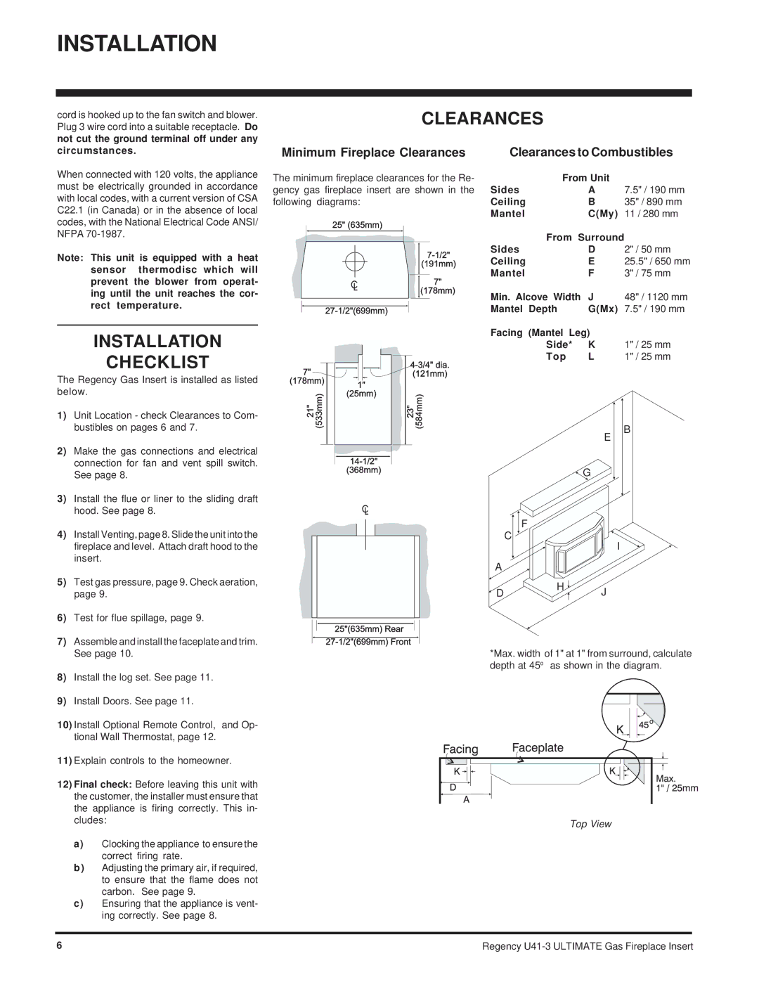
Minimum Fireplace Clearances
The minimum fireplace clearances for the Re- gency gas fireplace insert are shown in the following diagrams:
Clearances to Combustibles
| From Unit |
|
Sides | A | 7.5" / 190 mm |
Ceiling | B | 35" / 890 mm |
Mantel | C(My) | 11 / 280 mm |
| From Surround |
|
Sides | D | 2" / 50 mm |
Ceiling | E | 25.5" / 650 mm |
Mantel | F | 3" / 75 mm |
ing until the unit reaches the cor- rect temperature.
INSTALLATION
CHECKLIST
The Regency Gas Insert is installed as listed below.
1) | Unit Location - check Clearances to Com- |
| bustibles on pages 6 and 7. |
2) | Make the gas connections and electrical |
| connection for fan and vent spill switch. |
| See page 8. |
3) | Install the flue or liner to the sliding draft |
| hood. See page 8. |
4) | Install Venting, page 8. Slide the unit into the |
| fireplace and level. Attach draft hood to the |
| insert. |
Min. Alcove Width | J |
Mantel Depth | G(Mx) |
Facing (Mantel Leg)
Side* K
Top L
E
![]() G
G
F
C ![]()
I
A
48" / 1120 mm 7.5" / 190 mm
1" / 25 mm 1" / 25 mm
B
5) | Test gas pressure, page 9. Check aeration, | |
| page 9. | |
6) | Test for flue spillage, page 9. | |
7) | Assemble and install the faceplate and trim. | |
| See page 10. | |
8) | Install the log set. See page 11. | |
9) | Install Doors. See page 11. | |
10) Install Optional Remote Control, and Op- | ||
| tional Wall Thermostat, page 12. | |
11) Explain controls to the homeowner. | ||
12) Final check: Before leaving this unit with | ||
| the customer, the installer must ensure that | |
| the appliance is firing correctly. This in- | |
| cludes: | |
| a) | Clocking the appliance to ensure the |
|
| correct firing rate. |
| b) | Adjusting the primary air, if required, |
|
| to ensure that the flame does not |
|
| carbon. See page 9. |
| c) | Ensuring that the appliance is vent- |
|
| ing correctly. See page 8. |
H
D![]() J
J
*Max. width of 1" at 1" from surround, calculate depth at 45o as shown in the diagram.
Top View
6 | Regency |