INSTALLATION
GAS CONNECTION
For minimum and maximum supply pressure see the System Data table on page 7.
Note: Prior to any pressure testing of the gas supply piping system that exceeds test pressures of 1/2 psig, this appliance and its individ- ual
Valve Access: Loosen and remove the wing- nuts on the both sides of the bottom louver and then remove the louver.
2)The gas connection is a 3/8" NPT male pipe on the rear left side of the unit. The gas line can be rigid pipe or to make installation easier use a listed flexible connector and manual
3)Locate the center point where the vent will pass through the chimney above the appli- ance. Move the appliance into the exact location where it is to be installed. Ensure that the Insert is level.
4)The gas control valve is provided with two "IN" and "OUT" pressure taps, and are easily accessible for a test gauge connec- tion (see diagram on page 9).
5)Once the gas has been connected ensure that the pilot valve is in line with burner.
CAUTION: If the door is removed or opened for servicing, it must be replaced and closed prior to operating the appli- ance. The glass must be fixed in the door when operating.
DRAFT HOOD
CONNECTION
COMBUSTION &
VENTILATION AIR
WARNING: This appliance needs fresh air for safe operation and must be installed with provisions for adequate combus- tion and ventilation air available to the room in which it is to be operating.
Follow CAN/CGA B149 (in Canada) or ANSI Z223.1 (in the USA) requirements, and any local codes or regulations of the enforcing authority.
Air for combustion is drawn in through the front of the unit, therefore, the front of the unit must be kept clear of any obstructions.
VENTING
THEAPPLIANCEMUSTNOTBECON- NECTEDTOACHIMNEYFLUESERV- INGASEPARATESOLIDFUELBURN- ING APPLIANCE.
This appliance is designed to attach to a 4" diameter type
GAS CONNECTION WARNING: Only persons licensed to work with gas piping may make the necessary gas connections to this appliance.
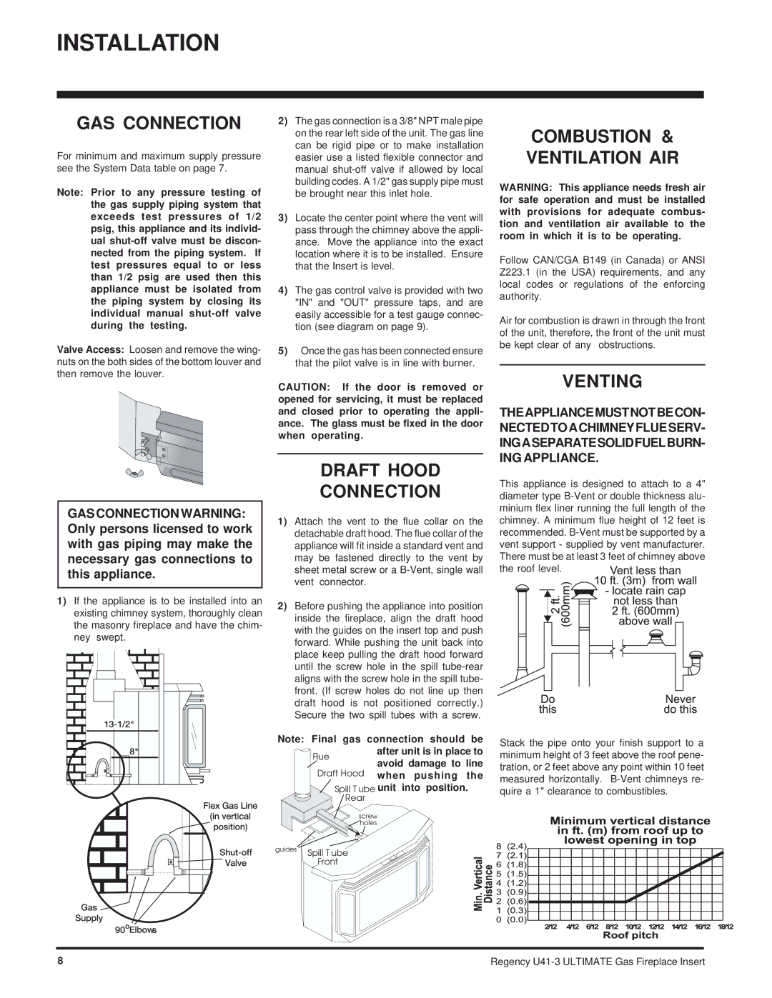
1)If the appliance is to be installed into an existing chimney system, thoroughly clean the masonry fireplace and have the chim- ney swept.
1)Attach the vent to the flue collar on the detachable draft hood. The flue collar of the appliance will fit inside a standard vent and may be fastened directly to the vent by sheet metal screw or a
2)Before pushing the appliance into position inside the fireplace, align the draft hood with the guides on the insert top and push forward. While pushing the unit back into place keep pulling the draft hood forward until the screw hole in the spill
Note: Final gas connection should be after unit is in place to
Flue
avoid damage to line when pushing the
 Spill T ube unit into position.
Rear
screw |
holes |
guides | Spill T ube |
| |
| Front |
chimney. A minimum flue height of 12 feet is recommended. ![]()
![]()
![]()
Stack the pipe onto your finish support to a minimum height of 3 feet above the roof pene- tration, or 2 feet above any point within 10 feet measured horizontally.
8 | Regency |