Tool Disassembly and
Assembly
TOOL ASSEMBLY
A. ATTACHING LINER TO TOOL BODY
1.Replace two ball bearings and springs into end of liner (see Figure 9, page 20).
2.Slide tool body onto liner.
3.Insert two screws into front of tool body just under liner. Tighten screws firmly.
B. ATTACHING TRIGGER ASSEMBLY TO TOOL BODY
1.Insert trigger assembly into tool body at rear of body (see Figure 8, page 20).
2.Replace trigger pin. Do this by inserting trigger pin through tool body and trigger assembly. After pin is inserted, tighten pin firmly using a standard screw driver.
C. ATTACHING FIRING PIN ASSEMBLY
1.Insert push pin into tool body (see item 11, page 17, for push pin location). Hole for push pin is located in cylinder at rear of tool. The hole for the push pin is located beside center hole in cylinder. Insert narrow end of pin first.
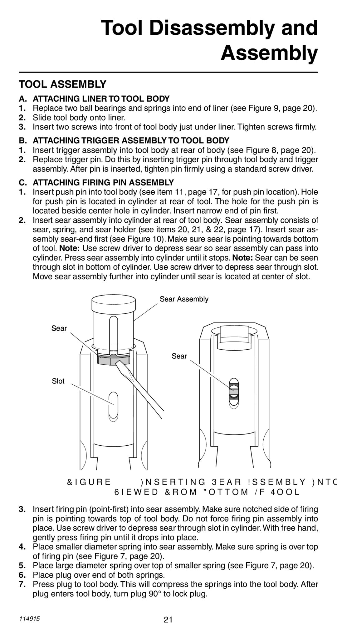
2.Insert sear assembly into cylinder at rear of tool body. Sear assembly consists of sear, spring, and sear holder (see items 20, 21, & 22, page 17). Insert sear as- sembly
Sear Assembly
Sear
Sear
Slot
Figure 10 - Inserting Sear Assembly Into Cylinder As
Viewed From Bottom Of Tool
3.Insert firing pin
4.Place smaller diameter spring into sear assembly. Make sure spring is over top of firing pin (see Figure 7, page 20).
5.Place large diameter spring over top of smaller spring (see Figure 7, page 20).
6.Place plug over end of both springs.
7.Press plug to tool body. This will compress the springs into the tool body. After plug enters tool body, turn plug 90° to lock plug.
114915 | 21 |
