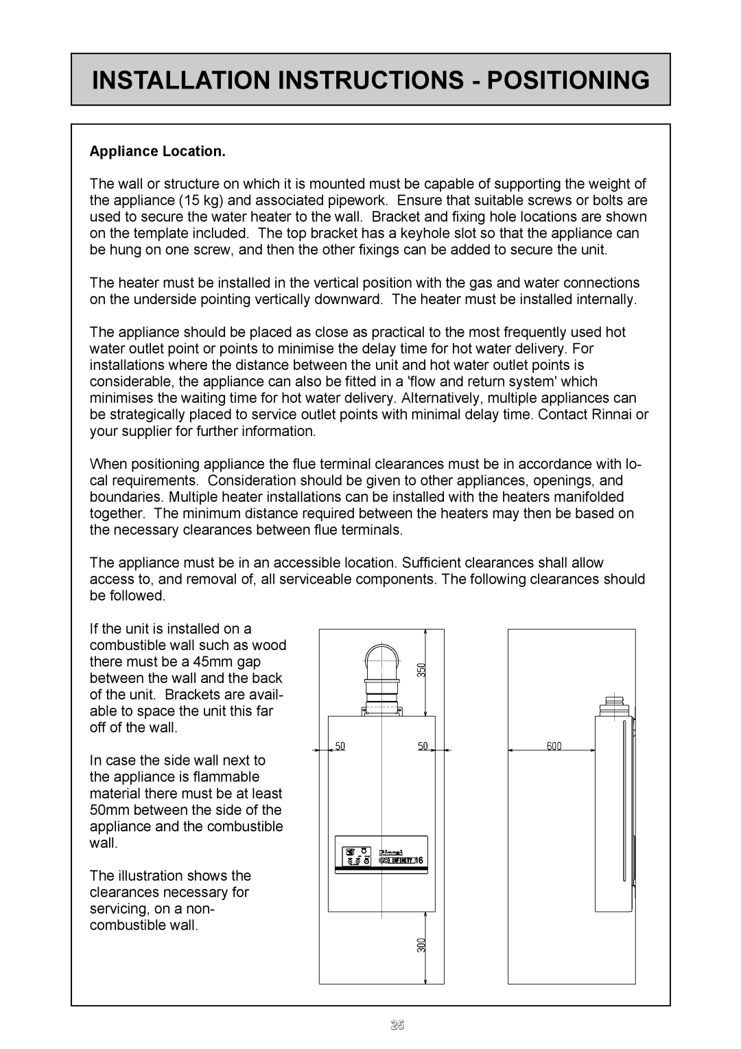
REU - 16 FUA - E specifications
The Rinnai REU-16 FUA-E is a cutting-edge tankless water heater designed for efficiency and convenience. This model is part of Rinnai's renowned line of high-performance appliances, catering to both residential and commercial applications. It boasts a sleek design coupled with advanced technology that sets it apart in the crowded water heating market.One of the most notable features of the REU-16 FUA-E is its impressive heating capacity. It is capable of delivering hot water on demand, with a maximum output of 16 liters per minute. This means you can comfortably run multiple hot water fixtures simultaneously without experiencing a drop in temperature or flow rate. Whether you’re taking a shower, running the dishwasher, or washing clothes, this unit meets the demand with ease.
The REU-16 FUA-E employs a state-of-the-art condensing technology, which enhances its efficiency by capturing and reusing some of the heat that would otherwise escape through the flue. This allows for an energy efficiency rating of up to 95%, significantly reducing energy bills and environmental impact compared to traditional storage water heaters.
Another key characteristic of this unit is its compact size. The Rinnai REU-16 FUA-E can be installed in smaller spaces, making it an ideal option for apartments, houses, or commercial properties with limited room for bulky tank units. Its flexibility in installation positions—whether indoors or outdoors—provides additional versatility to users.
Safety is also a primary concern with the REU-16 FUA-E. It comes equipped with numerous safety features, including an anti-freezing function, overheat protection, and venting safety controls. These safeguards ensure safe operation for you and your family, providing peace of mind whether it’s running constantly or in standby mode.
In terms of controls, the Rinnai REU-16 FUA-E offers modern digital displays that provide real-time monitoring of water temperature and status. This user-friendly interface makes it easier for homeowners or users to adjust settings according to their preferences.
Overall, the Rinnai REU-16 FUA-E encapsulates innovation and efficiency in water heating. Its combination of advanced technology, high performance, compact design, and safety features makes it a reliable choice for those seeking a consistent supply of hot water without the limitations of traditional systems. Whether for residential use or commercial applications, the REU-16 FUA-E is engineered to provide lasting performance and convenience.

