SECTION 7: OPTIONAL HEATER ACCESSORIES
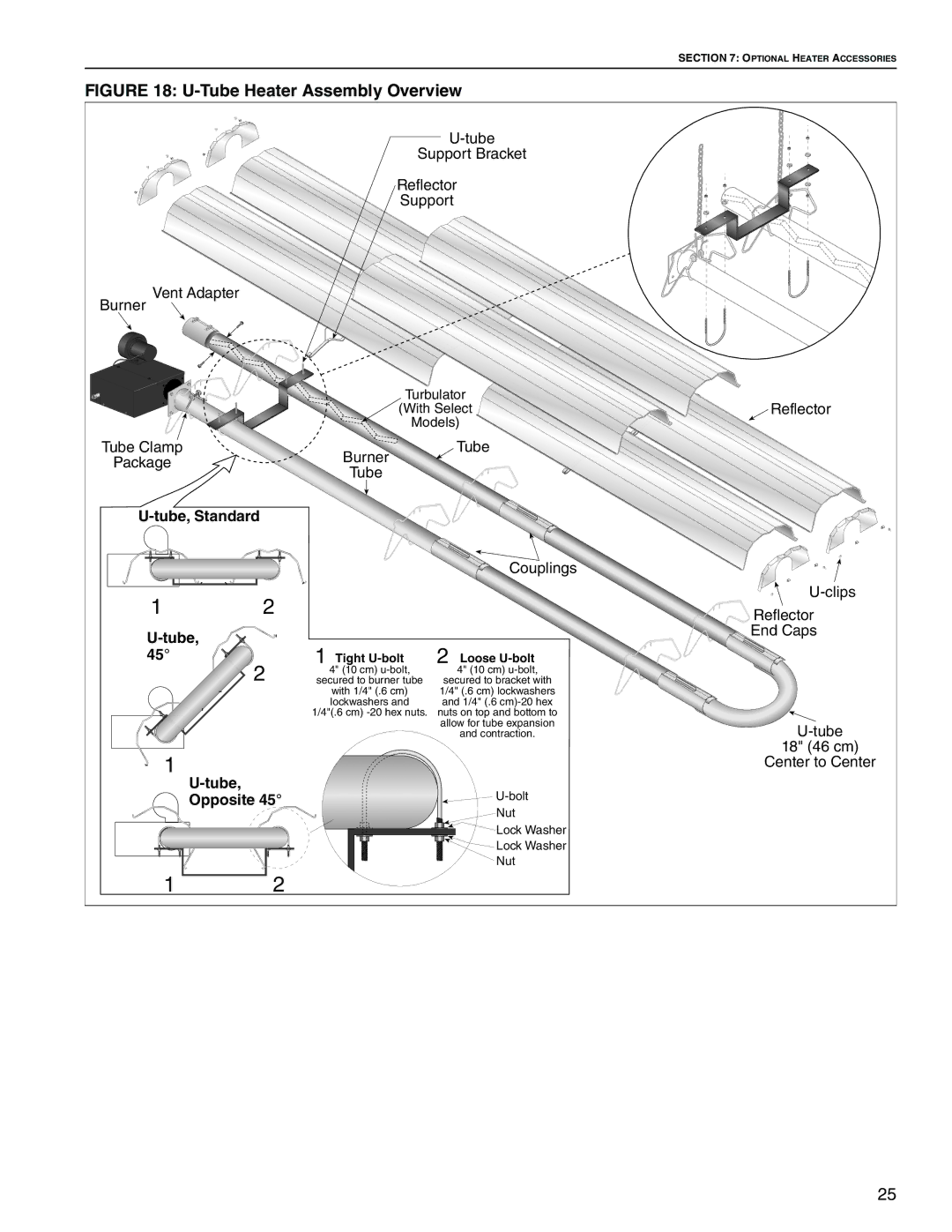
FIGURE 18: U-Tube Heater Assembly Overview
|
|
|
|
| |
|
|
| Support Bracket |
| |
|
|
| Reflector |
| |
|
|
| Support |
| |
Burner Vent Adapter |
|
|
|
|
|
|
|
| Turbulator | Reflector | |
|
|
| (With Select | ||
|
|
| Models) |
| |
Tube Clamp |
|
| Burner | Tube |
|
Package |
|
|
|
| |
|
| Tube |
|
| |
|
|
|
|
| |
|
|
|
| ||
|
|
|
| Couplings |
|
1 | 2 |
|
|
| |
|
|
| Reflector | ||
|
|
|
|
| End Caps |
| 1 |
|
|
| |
45° |
| Tight | Loose |
| |
| 2 | 4" (10 cm) | 2 4" (10 cm) |
| |
| secured to burner tube | secured to bracket with |
| ||
|
|
| with 1/4" (.6 cm) | 1/4" (.6 cm) lockwashers |
|
|
|
| lockwashers and | and 1/4" (.6 |
|
|
| 1/4"(.6 cm) |
| ||
|
|
|
| allow for tube expansion | |
|
|
|
| and contraction. | |
1 |
|
|
|
| 18" (46 cm) |
|
|
|
| Center to Center | |
|
|
|
| ||
Opposite 45° |
|
|
| ||
|
|
|
| Nut |
|
|
|
|
| Lock Washer |
|
|
|
|
| Lock Washer |
|
|
|
|
| Nut |
|
1 | 2 |
|
|
|
|
25