FIGURE 15 Linear Heater Assembly Overview
FIGURE 16 Linear Heater Layout Overview
per 20 6 m away from burner S-Hook Hanger
Step 6.1 Burner Tube Installation
Tubing requires a downward slope of 1/2 13 mm
Burner Tube 7 6 ± 229 cm ± 25 cm
Step 6.2 Tube Clamp Package Installation
Step 6.3 Coupling and Tube Assembly
Step 6.3.1 Coupling and Tube Assembly Continued
Step 6.3.2 Coupling and Tube Assembly Continued
± 2 5 cm
Step 6.4 Turbulator Installation
Step 6.5 Reflector Installation
Fire Hazard
Reflector must not touch tube
The pictorial drawings of the heater construction in Section 6 are schematic only and provide a general guideline of where hangers, reflector supports and U-clipsare to be installed
Extra chain min 12 30 cm
Step 6.6 Burner Installation
SECTION 6 HEATER INSTALLATION
Burner
Cut/Pinch Hazard
SECTION 7 OPTIONAL HEATER ACCESSORIES
7.1 U-TubeConfiguration
Edges are sharp
U-tube
FIGURE 18 U-TubeHeater Assembly Overview
U-tube,Standard
U-tube
FIGURE 19 U-TubeHeater Layout Overview
FIGURE 20 U-TubeLayout Overview Continued
Step 7.2.4 Reflector Joint Installation
Step 7.2.2 Elbow Installation
Step 7.2.3 Reflector Joint Installation
Reflector Reflector Joint
Step 7.2.5 Reflector Joint Detail
Install reflector
SECTION 7 OPTIONAL HEATER ACCESSORIES
FIGURE 21 Reflector Joint Detail
Step 7.3.1 Bracket Installation
Step 7.3.2 Side Reflector Installation
7.3 Reflector Side Extension
SECTION 7 OPTIONAL HEATER ACCESSORIES
7.4Lower Clearance Shield Installation
Step 7.4.1 Shield Support Strap Assembly
Description
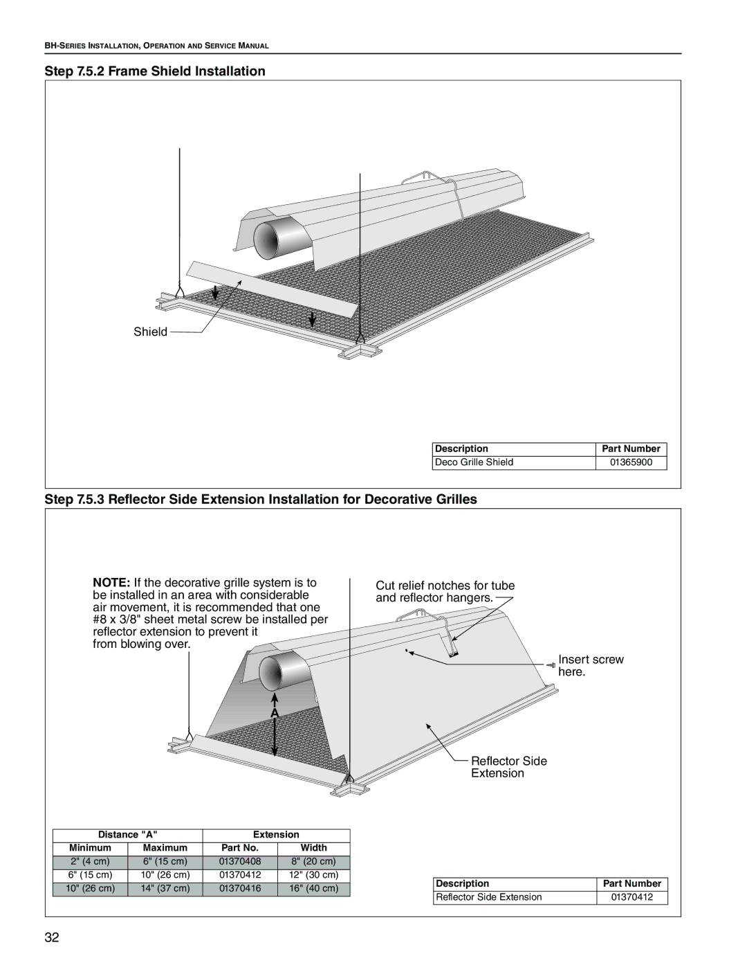
Step 7.5.2 Frame Shield Installation
Step 7.6.2 Grille End Cap Installation
Step 7.6.3 Grille Installation
Cut/Pinch Hazard
SECTION 8 VENTING
Carbon Monoxide Hazard
Edges are sharp
8.4 Vertical Venting
8.2 Unvented Operation
8.3 Horizontal Venting
8.5 Unvented Operation Tube Termination
SIDE VIEW
8.7 Horizontal Ventilation 4 10 cm Pipe
8.8 Vertical Ventilation 4 10 cm Pipe
Combustible or
8.9 Common Side Wall Venting
Requirements
Heaters must be of the same BTU output
8.10 Common Vertical Venting
Heaters must be of the same BTU output
Requirements
8.11 Outside Combustion Air Supply
8.11.1 Length Requirements
Requirements
Requirements
Fire Hazard
Gas hose can crack when twisted
SECTION 9 GAS PIPING
Gas hose moves during normal operation
FIGURE 23 Gas Connection with Flexible Gas Hose
when attaching gas hose
INCORRECT POSITIONS WRONG INSTALLATION
CORRECT POSITIONS
Disconnect electric before service or maintenance
DANGER
SECTION 10 WIRING
10.1 Line Voltage Thermostat Wiring
10.2 Low Voltage Thermostat Wiring
DSI Ignition Module BLUE
10.3 Internal Wiring
Pressure Switch
Electrode
Connect wires together with
before service or
SECTION 11 OPERATION AND MAINTENANCE
heater before service
during installation
For best performance, the gas, electrical, thermostat connections, tubing, venting, suspensions and overall heater condition should be inspected thoroughly
The Vicinity of the Heater
11.5 Maintenance Checklist
Installation Code and Annual Inspections
See Page 4, Section
Thermostat
Burner Cup and Orifice
Electrode
See Page 43, Section
heater before service
SECTION 12 TROUBLESHOOTING
Disconnect electric before service or maintenance
before service or
Troubleshooting Flow Chart
12.1
SECTION 12 TROUBLESHOOTING
12.2 Manifold Gas Pressure Setting
Natural Propane
Top View of Heater
SECTION 13 REPLACEMENT PARTS
DANGER
REAR VIEW
TOP VIEW
Description
Part Number
14.2 Heater Specifications 14.2.1 Ignition
SECTION 14 GENERAL SPECIFICATIONS
14.1 Material Specifications 14.1.1 Reflectors
DIMENSIONS
ROBERTS-GORDONLLC WILL NOT PAY FOR
WARRANTY IS VOID IF
ROBERTS-GORDONLLC WILL PAY FOR
LIMITATIONS ON AUTHORITY OF REPRESENTATIVES
Page
Purchased From if different than installer
OWNER WARRANTY REGISTRATION CARD
About the Installer
Type of Installation check one
Page
Page
the side
Maintain
clearance
clearance below