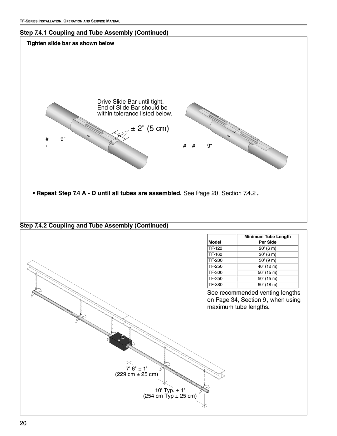
TF-380, TF-250, TF-160, TF-200, TF-120 specifications
Roberts Gorden is renowned for its innovative and efficient heating solutions, particularly through its TF series of forced air heaters. The TF-120, TF-200, TF-250, TF-300, and TF-350 models are designed to cater to a variety of applications, offering flexibility, efficiency, and user-friendly operation.The TF series features advanced combustion technology that ensures high thermal efficiency, significantly reducing fuel consumption while providing optimal heating performance. The heaters utilize a state-of-the-art burner design that allows for quiet operation and minimal emissions, aligning with modern environmental standards.
A standout feature across the TF series is the digital control system, which offers precise temperature management and programmability. The LCD interface allows users to easily adjust settings, monitor performance, and receive diagnostic feedback, enhancing reliability and operational efficiency. The automated controls save energy by modulating operation to only what is necessary to maintain the desired temperature.
The design of the TF-120, TF-200, TF-250, TF-300, and TF-350 models prioritizes durability and ease of installation. Built with rugged materials, these heaters can withstand demanding industrial environments while ensuring long service life. The compact footprint of each model allows for flexible placement, making them suitable for various facilities, including warehouses, workshops, and retail spaces.
Safety is a core attribute of the TF series. Each heater comes equipped with multiple safety features, including over-temperature protection, flame failure detection, and safety shut-off valves. This commitment to safety ensures that users can operate the heaters with peace of mind.
In terms of output capacity, the TF models range to accommodate different heating needs. The TF-120 is perfect for smaller spaces, while the TF-350 caters to larger areas, providing versatility for various industrial applications. Additionally, the heaters can be powered by natural gas or propane, offering flexibility in fuel choice based on user preference or availability.
In summary, Roberts Gorden's TF series—TF-120, TF-200, TF-250, TF-300, and TF-350—delivers a well-rounded heating solution with features such as high thermal efficiency, advanced digital controls, robust safety mechanisms, and a durable design. The adaptability and efficiency of these heaters make them a preferred choice for businesses seeking reliable heating solutions in diverse environments.

