Rockford Fosgate 250.2 manual About the Dynamic Power Measurements, Music, Information Cubed

Models: 250.2

1 61
Download 61 pages 48.59 Kb
Page 48
Image 48
DYNAMIC POWER MEASUREMENTS

DYNAMIC POWER MEASUREMENTS

About the Dynamic Power Measurements

The Audio Graph PowerCube is a test instrument used to measure the output of an amplifier in accordance with IHF-202 industry standards. The IHF-202 standard is a dynamic power measurement and was developed as a means of measuring power in a manner that best represents the Real World operation of an amplifier. Many manufacturers, including Rockford Fosgate, at times will measure amplifier power into a fixed resistor (4 ohm, 2 ohm). While this method is useful in some types of evaluation and testing, it is not representative of an amplifier that is connected to a speaker and playing music.

Music

Music is dynamic; the sound waves are complex and constantly changing. In order to simulate this, the IHF-202 standard calls for the input signal to the amplifier to be a 1kHz bursted tone. This signal is input (on for 20 milliseconds) and reduced 20dB for 480 milliseconds. The signal is gradually increased in level until the amplifier's output exceeds 1% Total Harmonic Distortion (THD). At 1% distortion becomes audible, therefore, any power produced above that level is considered unusable. Many manufacturers represent their amplifiers' output power in excess of 10% distortion. They use many names for this measurement, such as Total Maximum Power or Maximum Output Power. This is not indicative of the actual usable output power.

Listening to Loudspeakers - Not Resistors

A loudspeaker is not a resistor. A resistor's value (resistance measured in ohms) is fixed. A loudspeaker's impedance is dynamic. It is constantly changing in value, dependent upon the frequency of the input signal. Therefore, measuring power with the amplifier loaded into a 4 ohm resistor is not the same as measuring power with the amplifier connected to a 4 ohm speaker. Most people do not listen to music through a resistor.

A 4 ohm speaker may experience a drop in impedance 4-6 times lower than its nominal (printed) impedance. A speaker will also create phase shifts in the signal that is passed through it. These phase shifts happen because a speaker is an inductor (voice coil) and a capacitor (compliance of the surround/spider), as well as a resistor (voice coil wire).

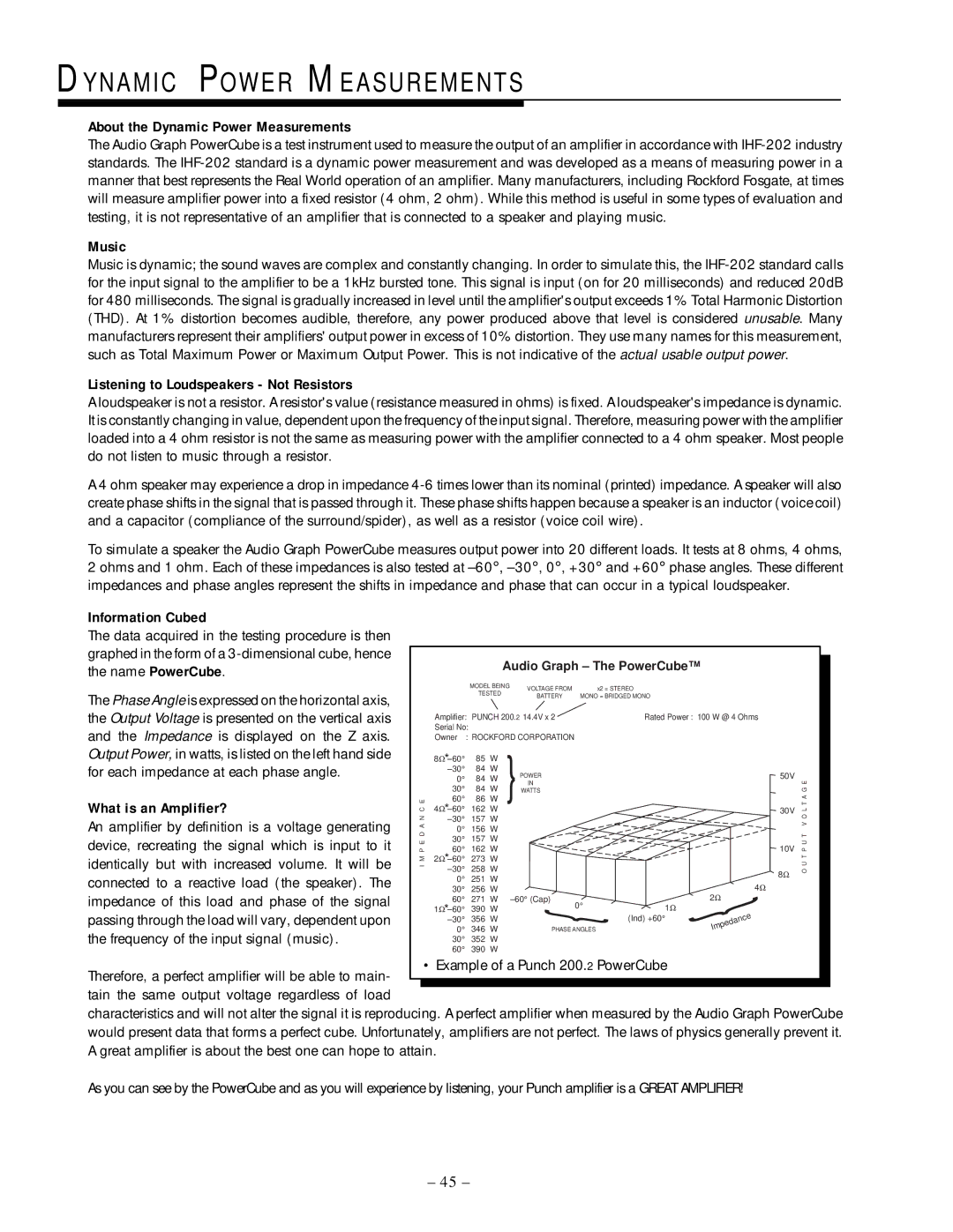
To simulate a speaker the Audio Graph PowerCube measures output power into 20 different loads. It tests at 8 ohms, 4 ohms, 2 ohms and 1 ohm. Each of these impedances is also tested at –60°, –30°, 0°, +30° and +60° phase angles. These different impedances and phase angles represent the shifts in impedance and phase that can occur in a typical loudspeaker.

Information Cubed


The data acquired in the testing procedure is then


graphed in the form of a 3-dimensional cube, hence


Audio Graph – The PowerCube™


the name PowerCube.


MODEL BEING

VOLTAGE FROM


x2 = STEREO


The Phase Angle is expressed on the horizontal axis,


TESTED


BATTERY

MONO = BRIDGED MONO


the Output Voltage is presented on the vertical axis


Amplifier: PUNCH 200.2 14.4V x 2


Rated Power : 100 W @ 4 Ohms


and the Impedance is displayed on the Z axis.


Serial No:


Owner

: ROCKFORD CORPORATION


Output Power, in watts, is listed on the left hand side


8Ω*–60°

85

W


for each impedance at each phase angle.


–30°

84

W


POWER


50V


0°

84

W


G E


IN


30°


84

W

{WATTS


What is an Amplifier?

C E

60°

86

W


A


4Ω*–60°

162

W


30V

L T


An amplifier by definition is a voltage generating

N

–30°

157

W


O


A


V


0°

156

W


P E D


P U T


device, recreating the signal which is input to it

30°

157

W


60°

162

W


10V


identically but with increased volume. It will be

M

2Ω*–60°

273

W


T


O U


I

–30°

258

W


8Ω


connected to a reactive load (the speaker). The


0°

251

W


4Ω


30°

256

W


impedance of this load and phase of the signal


60°

271

W


–60°(Cap)

0°


2Ω


1Ω*–60°

390

W


1Ω

{


passing through the load will vary, dependent upon


–30°

356

W


(Ind) +60°


the frequency of the input signal (music).


0°

346

W


PHASE{ANGLES

Impedance


30°

352

W


60°

390

W


Therefore, a perfect amplifier will be able to main-


• Example of a Punch 200.2 PowerCube


tain the same output voltage regardless of load


characteristics and will not alter the signal it is reproducing. A perfect amplifier when measured by the Audio Graph PowerCube would present data that forms a perfect cube. Unfortunately, amplifiers are not perfect. The laws of physics generally prevent it. A great amplifier is about the best one can hope to attain.

As you can see by the PowerCube and as you will experience by listening, your Punch amplifier is a GREAT AMPLIFIER!

– 45 –

Page 48
Image 48
Rockford Fosgate 250.2 manual About the Dynamic Power Measurements, Music, Listening to Loudspeakers - Not Resistors