INSTALLATION
INSTALLER: Leave these instructions with the appliance.
TOOL LIST
1.18” drill brt
2.Electric or hand drill
3.Flat bladed screwdriver
4.No 1 or No. 2 Phillips screwdriver
5.Pencil
6.Ruler and straight edge
7.Hand saw or saber saw
8.Pipe wrench
9.5’8” wrench and 112” wrench or adjustable wrench
10.:3116” hex socket driver
LOCATION
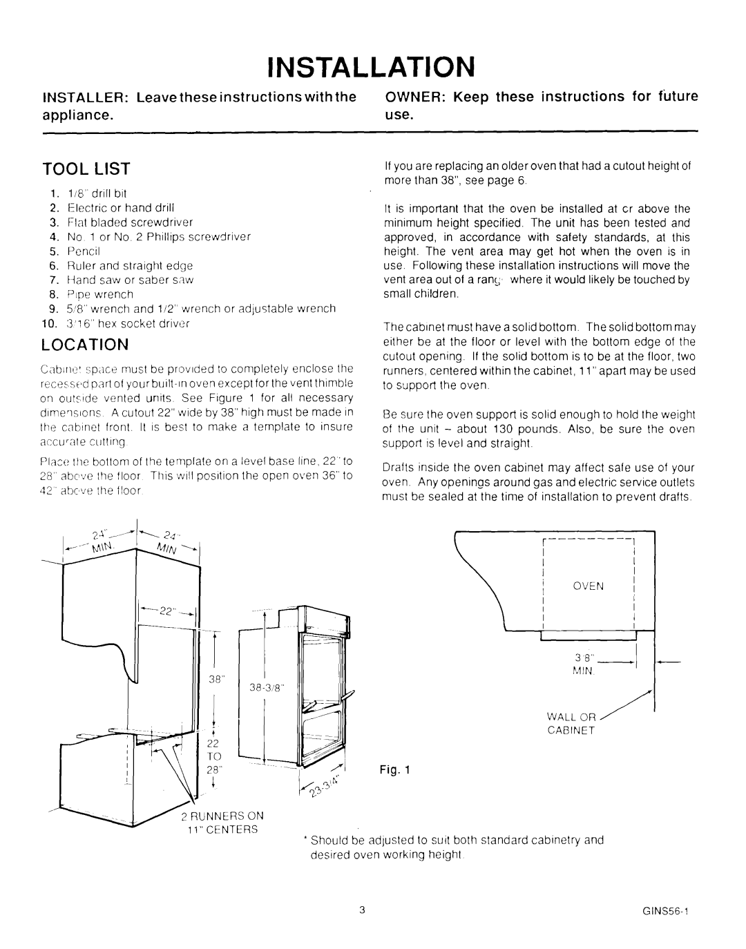
C,~brie’ sp,ice must be provided to completely enclose the recessed pan of your
Place the bottom of the template on a level base line, 22 ‘to 28” abc$Je lhe floor This :vIII posrtion the open oven 36” to 42 abc~ve the floor
OWNER: Keep these nstructions for future use.
If you are replacing an older oven that had a cutout height of more than 38”, see page 6.
It is important that the oven be installed at cr above the minimum height specified. The unit has been tested and approved, in accordance with safety standards, at this height. The vent area may get hot when the oven is in use. Following these installation instructions will move the vent area out of a ran!; where it would likely be touched by small children.
The cabinet must have a solid bottom. The solid bottom may either be at the floor or level with the bottom edge of the cutout opening. If the solid bottom is to be at the floor, two runners, centered within the cabinet, 1l”apart may be used to support the oven.
Be sure the oven support is solid enough to hold the weight of the unit - about 130 pounds. Also, be sure the oven support is level and straight.
Drafts inside the oven cabinet may affect safe use of your oven. Any openings around gas and electric service outlets must be sealed at the time of installation to prevent drafts.
r | |
|
OVEN
\j
3 0,’
M IN
I
WALL OR /
CABINET
Fig. 1
*Should be adjusted to suit both standard cabinetry and desired oven working height