RC-1550 specifications
The Rotel RC-1550 is a high-performance stereo preamplifier that showcases the brand's commitment to audio excellence and innovation. Designed for audiophiles who demand superior sound quality, this preamplifier delivers outstanding performance and a range of features that make it stand out in the competitive audio market.One of the defining characteristics of the RC-1550 is its robust build quality. Constructed with a rigid chassis that minimizes resonance and interference, the device ensures a clean audio signal. The component selection is equally impressive, utilizing high-quality capacitors and resistors to maintain audio integrity and clarity.
At the heart of the RC-1550 is Rotel's proprietary Class A/B amplification technology. This design approach allows for a more efficient power management system while maintaining the rich, warm tones and dynamic range that audiophiles crave. The result is an engaging listening experience with accurate sound reproduction across various genres of music.
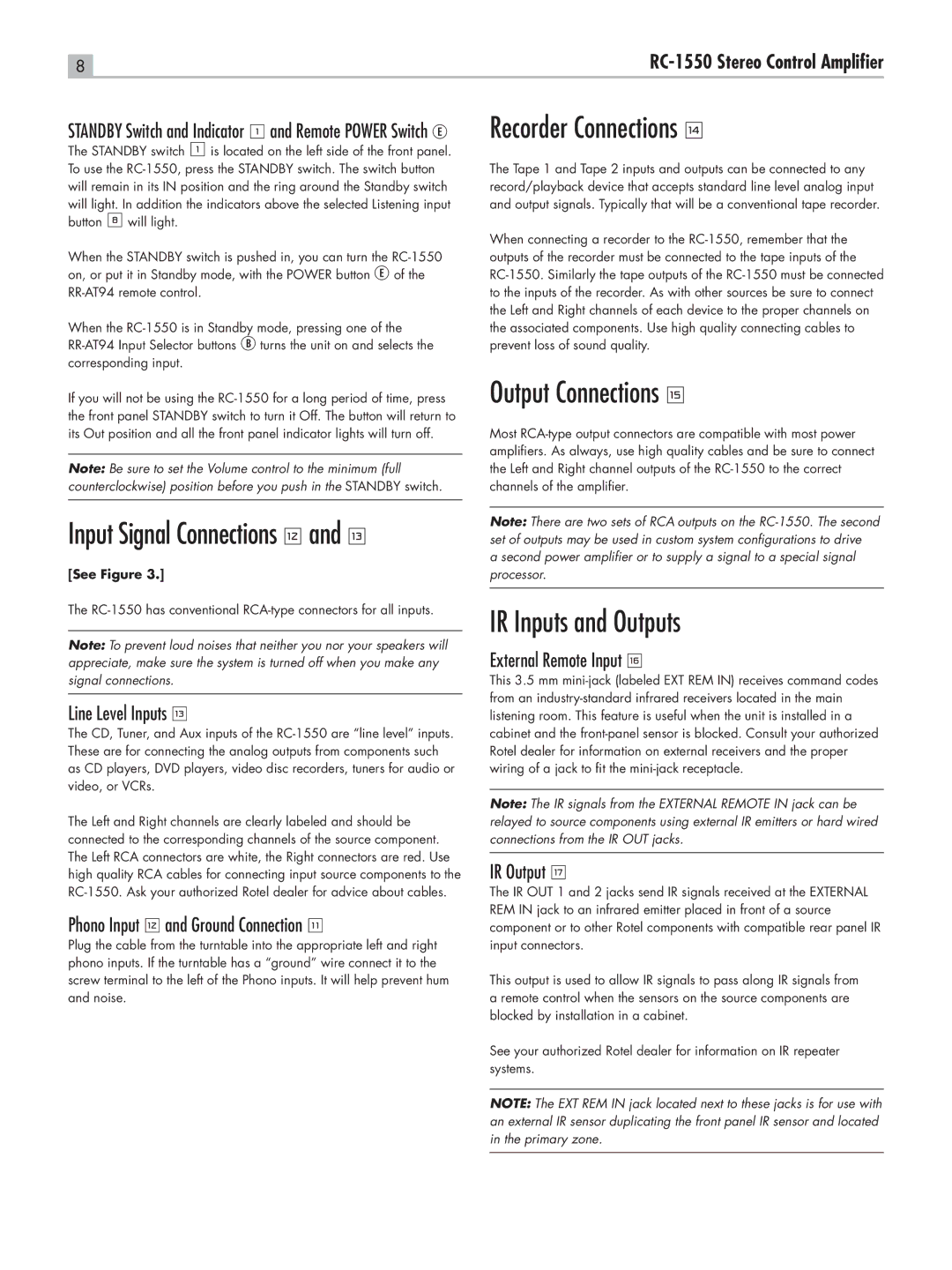
The preamplifier features a comprehensive range of inputs and outputs, allowing for seamless integration into any audio setup. With balanced XLR inputs and outputs, as well as unbalanced RCA connections, the RC-1550 offers versatility for connecting to a wide array of audio sources. It also includes a dedicated phono stage for vinyl enthusiasts, ensuring that every nuance of a record is captured with precision.
In addition to its input options, the RC-1550 incorporates advanced digital signal processing capabilities. It supports various digital audio formats, enabling users to connect to high-resolution sources and enjoy audiophile-quality sound from streaming services, CD players, or home theater systems. An intuitive front panel and a remote control enhance user experience by providing easy access to settings and sources.
Furthermore, the RC-1550 prioritizes convenience with features like a headphone output for private listening and customizable settings that allow users to fine-tune their audio experience. The thoughtful layout and high-quality components culminate in a preamplifier that not only delivers exceptional performance but also adds aesthetic value to any audio system.
In summary, the Rotel RC-1550 is a sophisticated stereo preamplifier that combines advanced technologies, premium materials, and meticulous engineering. Its features, including Class A/B amplification, multiple input options, and digital processing capabilities, make it an ideal choice for audiophiles seeking an elevated listening experience. Whether paired with high-end speakers or used in a home theater setup, the RC-1550 promises to deliver a remarkable audio experience.

