Runco
Installation
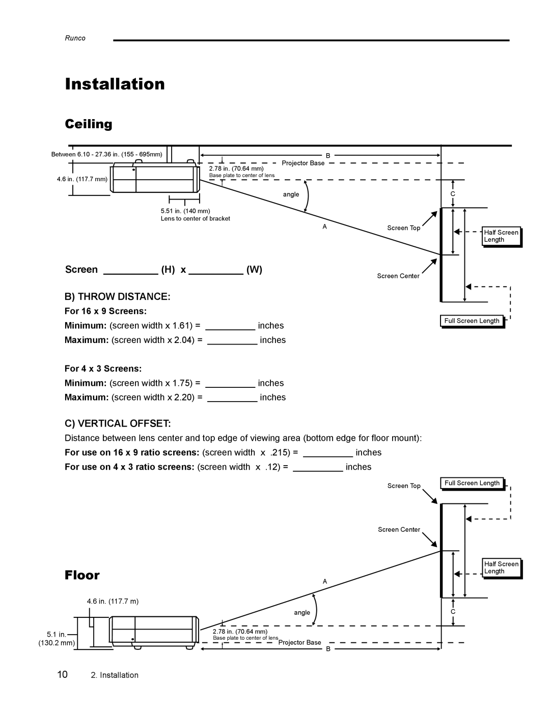
Ceiling
Between 6.10 - 27.36 in. (155 - 695mm) |
|
| 2.78 in. (70.64 mm) |
4.6 in. (117.7 mm) | Base plate to center of lens |
|
5.51 in. (140 mm)
Lens to center of bracket
Screen __________ (H) x __________ (W)
B) THROW DISTANCE:
B
Projector Base
angle
AScreen Top
Screen Center
C
Half Screen
Length
For 16 x 9 Screens:
Minimum: (screen width x 1.61) = __________ inches
Maximum: (screen width x 2.04) = __________ inches
For 4 x 3 Screens:
Minimum: (screen width x 1.75) = __________ inches
Maximum: (screen width x 2.20) = __________ inches
C) VERTICAL OFFSET:
Distance between lens center and top edge of viewing area (bottom edge for floor mount): For use on 16 x 9 ratio screens: (screen width x .215) = __________ inches
For use on 4 x 3 ratio screens: (screen width x .12) = __________ inches
Screen Top
![]()
![]() Full Screen Length
Full Screen Length ![]()
![]()
![]()
![]() Full Screen Length
Full Screen Length ![]()
![]()
Floor
4.6 in. (117.7 m)
5.1 in.
(130.2 mm)
Screen Center
A
angle
2.78 in. (70.64 mm)
Base plate to center of lensProjector Base
B
Half Screen |
Length |
C |
102. Installation