Runco
Location
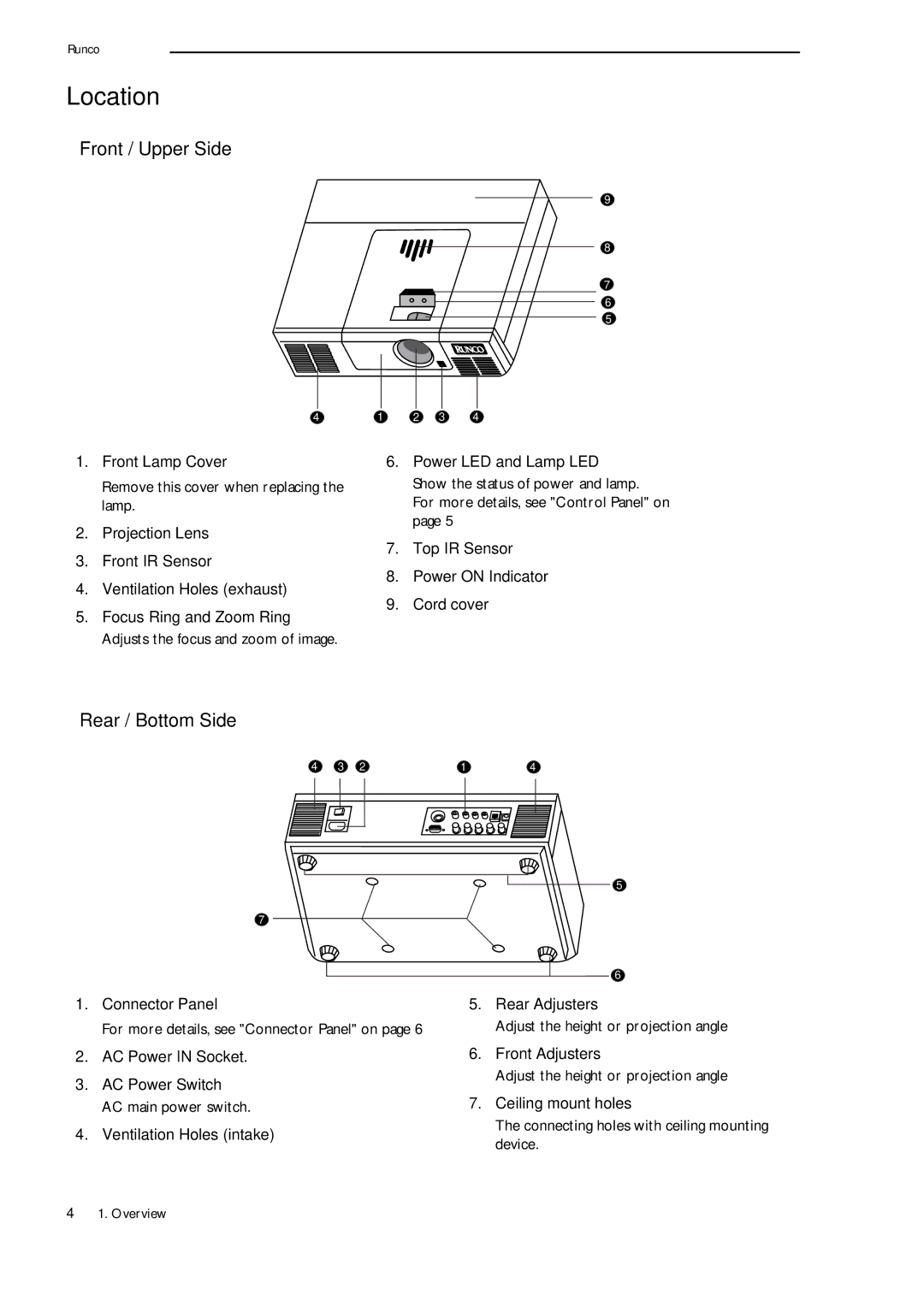
❚Front / Upper Side
9
8
7
6
5
4 | 1 | 2 | 3 | 4 |
1.Front Lamp Cover
Remove this cover when replacing the lamp.
2.Projection Lens
3.Front IR Sensor
4.Ventilation Holes (exhaust)
5.Focus Ring and Zoom Ring Adjusts the focus and zoom of image.
6.Power LED and Lamp LED Show the status of power and lamp.
For more details, see "Control Panel" on page 5
7.Top IR Sensor
8.Power ON Indicator
9.Cord cover
❚Rear / Bottom Side
4 3 2
7
1.Connector Panel
For more details, see "Connector Panel" on page 6
2.AC Power IN Socket.
3.AC Power Switch AC main power switch.
4.Ventilation Holes (intake)
14
5
6
5.Rear Adjusters
Adjust the height or projection angle
6.Front Adjusters
Adjust the height or projection angle
7.Ceiling mount holes
The connecting holes with ceiling mounting device.
41. Overview