Installation
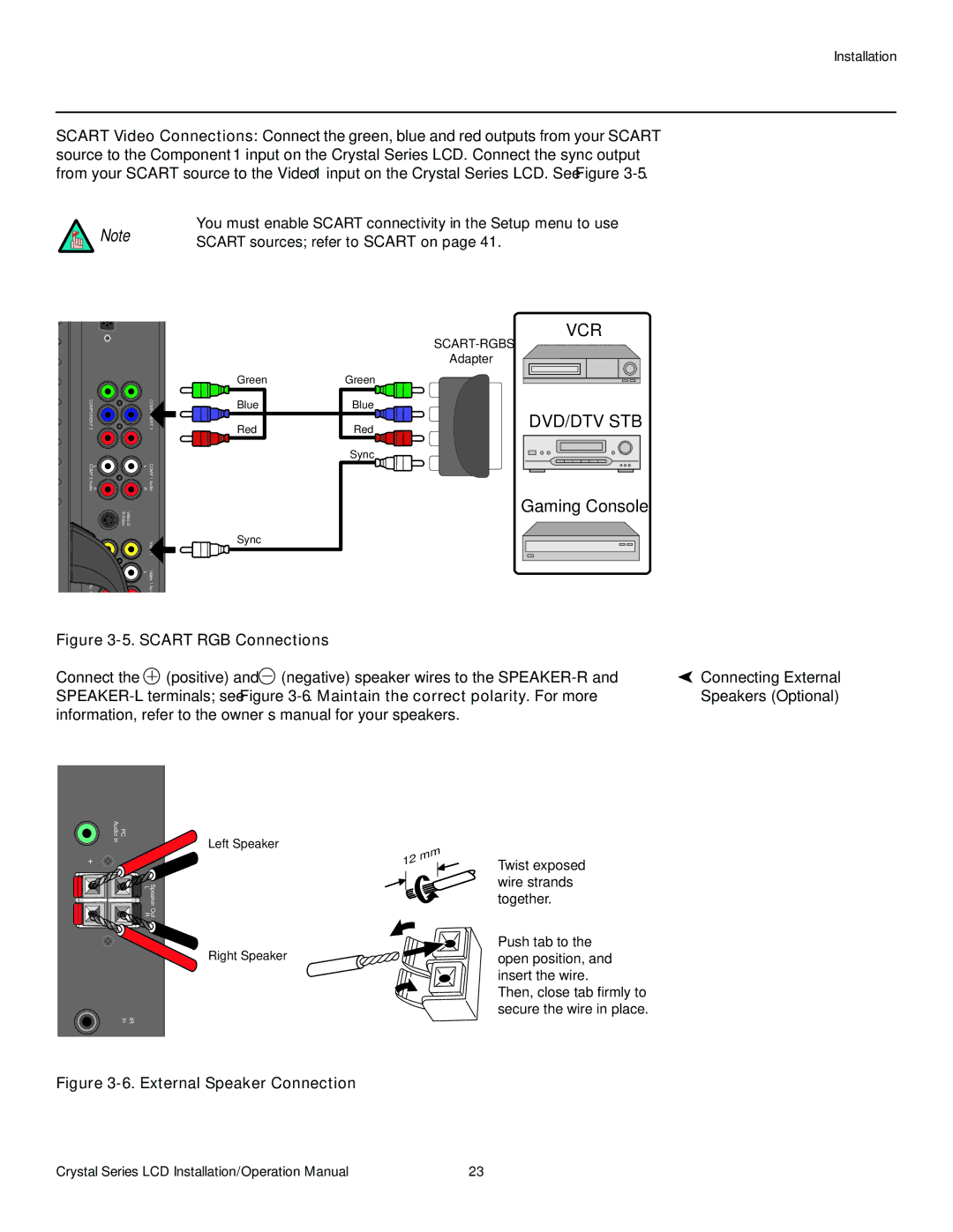
SCART Video Connections: Connect the green, blue and red outputs from your SCART source to the Component 1 input on the Crystal Series LCD. Connect the sync output from your SCART source to the Video 1 input on the Crystal Series LCD. See Figure
You must enable SCART connectivity in the Setup menu to use
Note | SCART sources; refer to SCART on page 41. |
|
COMPONENT 2 |
| COMPONENT 1 |
L COMP | L | COMP |
R 2 Audio | R | 1 Audio |
Video 2/ |
| |
Video 2 |
| 1 |
L Video | L | Video |
2 Aud |
| 1 Aud |
Green
Blue
Red
Sync
Green
Blue
Red
Sync
VCR
Adapter
DVD/DTV STB
Gaming Console
Figure |
| ||
Connect the | (positive) and | (negative) speaker wires to the | Connecting External |
Speakers (Optional) | |||
information, refer to the owner’s manual for your speakers. |
| ||
Audio | PC |
In | Left Speaker |
+ | – |
Speaker Out
L R
Right Speaker
IR
In
Figure 3-6. External Speaker Connection
Twist exposed wire strands together.
Push tab to the open position, and insert the wire.
Then, close tab firmly to secure the wire in place.
Crystal Series LCD Installation/Operation Manual | 23 |