Proceed as follows to connect the PlasmaWall to the DHD Controller, your video sources, external controller(s) – if present – and AC power.
When connecting your equipment:
•Turn off all equipment before making any connections.
•Use the correct signal cables for each source.
•Ensure that the cables are securely connected. Tighten the thumbscrews on connectors that have them.
3.4
Connections to the PlasmaWall and DHD Controller
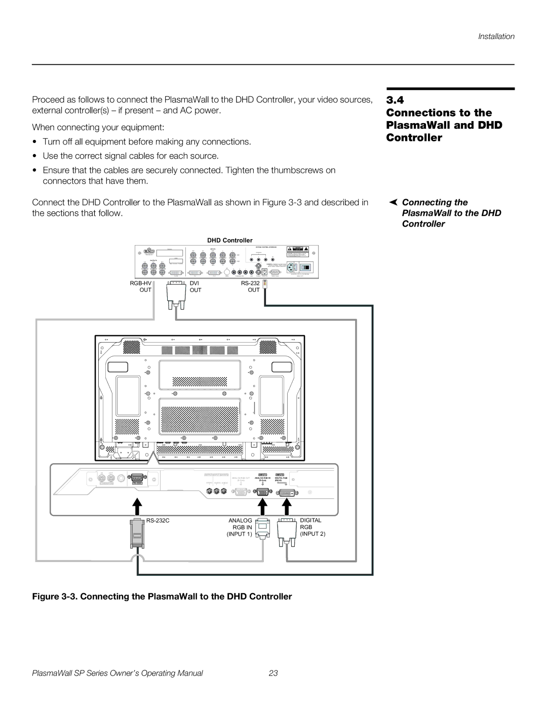
Connect the DHD Controller to the PlasmaWall as shown in Figure
DHD Controller
|
|
|
| SYSTEM CONTROL INTERFACE | ! |
Serial No |
| INPUTS |
|
| |
R/Pr | G/Y | B/Pb | H | V |
|
|
|
|
| TRIGGERS |
|
Runco International |
|
|
|
|
|
|
|
|
|
|
|
|
| |
Union City, CA |
|
|
|
|
|
|
| HD1 |
|
|
|
|
| |
|
|
| Model |
|
|
|
|
|
| 1 | 2 | 3 | IR |
|
|
|
|
|
|
|
|
|
|
|
|
|
|
| |
| OUTPUTS |
|
|
|
|
|
|
| HD2 |
|
|
|
|
|
R/Pr | G/Y | B/Pb |
|
|
|
|
|
|
|
|
|
|
| |
|
|
| Video Processor / Controller | R/Pr | G/Y | B/Pb | H | V |
|
|
| WARNING: |
| |
|
|
|
|
|
|
|
|
|
| |||||
|
|
|
|
|
|
| SDI | Pb | Pr | Y |
|
|
| |
|
|
|
|
|
|
|
|
|
|
|
|
|
| |
H | V | H/V | DVI Out | DVI 1 |
| DVI 2 | Option |
| Component Video | Video | Made In USA | |||
| DVI | ||
| |||
OUT |
| OUT | OUT |
|
|
|
|
 Connecting the
PlasmaWall to the DHD
Controller
IN OUT
COMBINATION
| OUTPUT | INPUT1 INPUT2 | INPUT1 | INPUT2 |
|
| ANALOG RGB OUT | ANALOG RGB IN | DIGITAL RGB |
|
| |||
AUDIO | AUDIO AUDIO |
|
|
ANALOG |
|
|
|
|
|
|
| DIGITAL | |
| RGB IN |
|
|
|
|
|
|
| RGB |
| (INPUT 1) |
|
|
|
|
|
|
| (INPUT 2) |
|
|
|
|
|
|
|
|
|
|
Figure 3-3. Connecting the PlasmaWall to the DHD Controller
PlasmaWall SP Series Owner’s Operating Manual | 23 |