FEATURES
RESET BUTTON
See Figure 2.
The router table switch is equipped with a reset button that protects the electronic components of the router table switch box from overload.
STARTING PIN
When you are unable to use the fence for a guide because the workpiece is
THROAT PLATES
Five throat plates are included with the router table. The throat plate provides a stable surface around the cutter and prevents objects from falling through the throat and damag- ing the spindle.
VACUUM PORT
The vacuum ports molded into the fence will accept either a
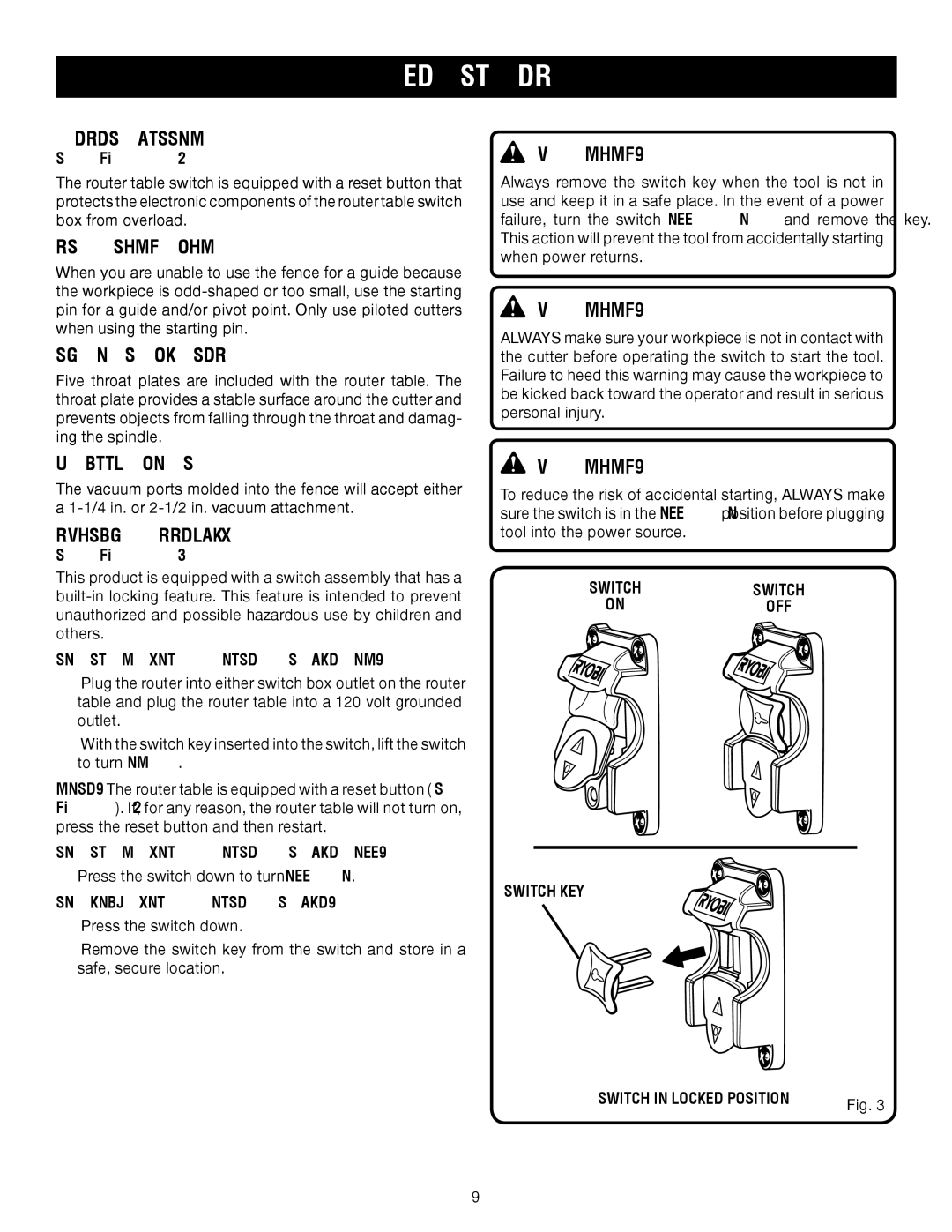
SWITCH ASSEMBLY
See Figure 3.
This product is equipped with a switch assembly that has a
TO TURN YOUR ROUTER TABLE ON:
Plug the router into either switch box outlet on the router table and plug the router table into a 120 volt grounded outlet.
With the switch key inserted into the switch, lift the switch to turn ON ( l ).
NOTE: The router table is equipped with a reset button ( See Figure 2 ). If, for any reason, the router table will not turn on, press the reset button and then restart.
TO TURN YOUR ROUTER TABLE OFF:
Press the switch down to turn OFF ( O ).
TO LOCK YOUR ROUTER TABLE:
Press the switch down.
Remove the switch key from the switch and store in a safe, secure location.
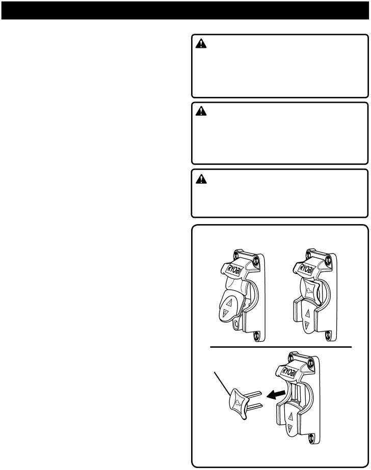
WARNING:
Always remove the switch key when the tool is not in use and keep it in a safe place. In the event of a power failure, turn the switch OFF ( O ) and remove the key. This action will prevent the tool from accidentally starting when power returns.
WARNING:
ALWAYS make sure your workpiece is not in contact with the cutter before operating the switch to start the tool. Failure to heed this warning may cause the workpiece to be kicked back toward the operator and result in serious personal injury.
WARNING:
To reduce the risk of accidental starting, ALWAYS make sure the switch is in the OFF ( O ) position before plugging tool into the power source.
SWITCH | SWITCH |
ON | OFF |
SWITCH KEY
SWITCH IN LOCKED POSITION | Fig. 3 |
|
9