ADJUSTMENTS
![]() WARNING:
WARNING:
To avoid personal injury, maintain proper adjustment of blade tension, blade guides, and thrust bearings.
nTo check tension, raise the blade guide assembly all the way up to expose the blade.
nPush the blade to the side with moderate force; the blade should flex approximately 1/8 in. (3 mm).
ADJUSTING THRUST BEARINGS, BLADE GUIDE SUPPORT, AND BLADE GUIDES
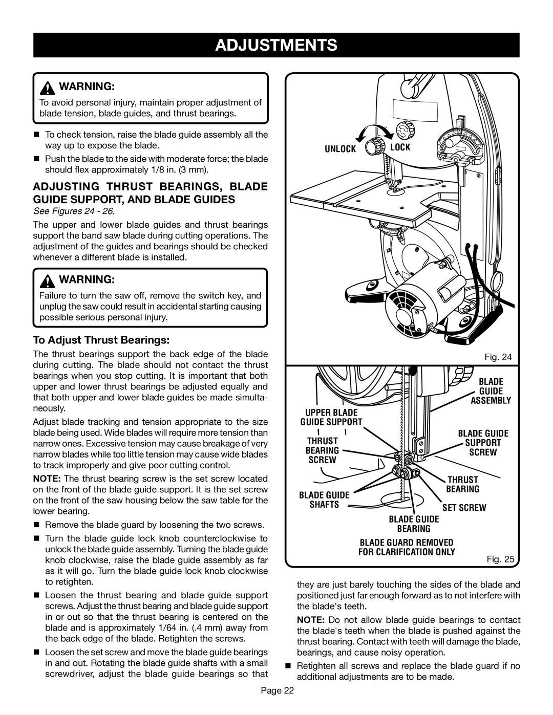
See Figures 24 - 26.
The upper and lower blade guides and thrust bearings support the band saw blade during cutting operations. The adjustment of the guides and bearings should be checked whenever a different blade is installed.
![]() WARNING:
WARNING:
Failure to turn the saw off, remove the switch key, and unplug the saw could result in accidental starting causing possible serious personal injury.
To Adjust Thrust Bearings:
The thrust bearings support the back edge of the blade during cutting. The blade should not contact the thrust bearings when you stop cutting. It is important that both upper and lower thrust bearings be adjusted equally and that both upper and lower blade guides be made simulta- neously.
Adjust blade tracking and tension appropriate to the size blade being used. Wide blades will require more tension than narrow ones. Excessive tension may cause breakage of very narrow blades while too little tension may cause wide blades to track improperly and give poor cutting control.
NOTE: The thrust bearing screw is the set screw located on the front of the blade guide support. It is the set screw on the front of the saw housing below the saw table for the lower bearing.
nRemove the blade guard by loosening the two screws.
nTurn the blade guide lock knob counterclockwise to unlock the blade guide assembly. Turning the blade guide knob clockwise, raise the blade guide assembly as far as it will go. Turn the blade guide lock knob clockwise to retighten.
nLoosen the thrust bearing and blade guide support screws. Adjust the thrust bearing and blade guide support in or out so that the thrust bearing is centered on the blade and is approximately 1/64 in. (.4 mm) away from the back edge of the blade. Retighten the screws.
nLoosen the set screw and move the blade guide bearings in and out. Rotating the blade guide shafts with a small screwdriver, adjust the blade guide bearings so that
UNLOCK  LOCK
LOCK
Fig. 24
|
| BLADE |
|
| GUIDE |
|
| ASSEMBLY |
UPPER BLADE |
|
|
GUIDE SUPPORT |
| |
THRUST |
| BLADE GUIDE |
| SUPPORT | |
BEARING |
| SCREW |
SCREW |
|
|
| THRUST | |
BLADE GUIDE | BEARING | |
|
| |
SHAFTS | SET SCREW | |
| ||
| BLADE GUIDE |
|
| BEARING |
|
| BLADE GUARD REMOVED |
|
| FOR CLARIFICATION ONLY | Fig. 25 |
|
| |
they are just barely touching the sides of the blade and positioned just far enough forward as to not interfere with the blade's teeth.
NOTE: Do not allow blade guide bearings to contact the blade's teeth when the blade is pushed against the thrust bearing. Contact with teeth will damage the blade, bearings, and cause noisy operation.
nRetighten all screws and replace the blade guard if no additional adjustments are to be made.
Page 22