FEATURES
TRIGGER LOCK
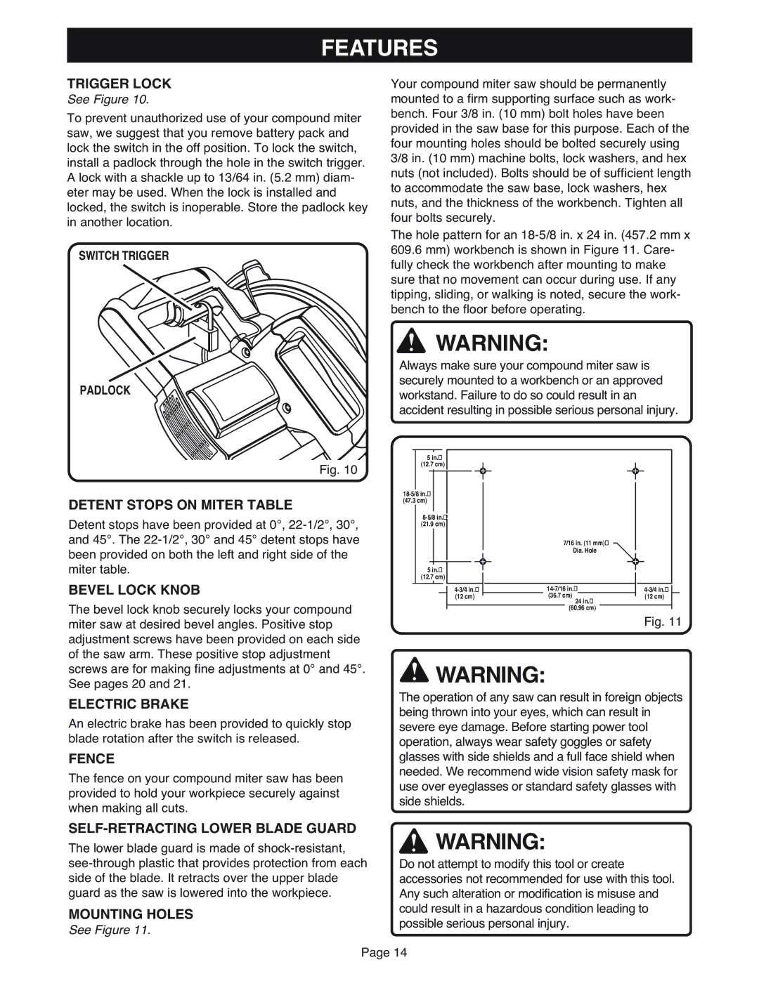
See Figure 10.
To prevent unauthorized use of your compound miter saw, we suggest that you remove battery pack and lock the switch in the off position. To lock the switch, install a padlock through the hole in the switch trigger. A lock with a shackle up to 13/64 in. (5.2 mm) diam- eter may be used. When the lock is installed and locked, the switch is inoperable. Store the padlock key in another location.
SWITCH TRIGGER
PADLOCK
Your compound miter saw should be permanently mounted to a firm supporting surface such as work- bench. Four 3/8 in. (10 mm) bolt holes have been provided in the saw base for this purpose. Each of the four mounting holes should be bolted securely using 3/8 in. (10 mm) machine bolts, lock washers, and hex nuts (not included). Bolts should be of sufficient length to accommodate the saw base, lock washers, hex nuts, and the thickness of the workbench. Tighten all four bolts securely.
The hole pattern for an
609.6mm) workbench is shown in Figure 11. Care- fully check the workbench after mounting to make sure that no movement can occur during use. If any tipping, sliding, or walking is noted, secure the work- bench to the floor before operating.
![]() WARNING:
WARNING:
Always make sure your compound miter saw is securely mounted to a workbench or an approved workstand. Failure to do so could result in an accident resulting in possible serious personal injury.
Fig. 10
DETENT STOPS ON MITER TABLE
Detent stops have been provided at 0°,
BEVEL LOCK KNOB
The bevel lock knob securely locks your compound miter saw at desired bevel angles. Positive stop adjustment screws have been provided on each side of the saw arm. These positive stop adjustment
5in.
(12.7 cm)
(4718”.3 cm)
(21.9 cm)
5in.
(12.7 cm)
(12 cm)
7/167/16”in. DIA(11 .mm)HOLE
Dia. Hole
(36.7 cm) |
| (12 cm) |
|
|
|
|
| ||
24 in. |
|
|
| |
(60.96 cm) |
|
|
| |
|
| Fig. 11 | ||
screws are for making fine adjustments at 0° and 45°. See pages 20 and 21.
ELECTRIC BRAKE
An electric brake has been provided to quickly stop blade rotation after the switch is released.
FENCE
The fence on your compound miter saw has been provided to hold your workpiece securely against when making all cuts.
![]() WARNING:
WARNING:
The operation of any saw can result in foreign objects being thrown into your eyes, which can result in severe eye damage. Before starting power tool operation, always wear safety goggles or safety glasses with side shields and a full face shield when needed. We recommend wide vision safety mask for use over eyeglasses or standard safety glasses with side shields.
SELF-RETRACTING LOWER BLADE GUARD
The lower blade guard is made of
MOUNTING HOLES
See Figure 11.
![]() WARNING:
WARNING:
Do not attempt to modify this tool or create accessories not recommended for use with this tool. Any such alteration or modification is misuse and could result in a hazardous condition leading to possible serious personal injury.
Page 14