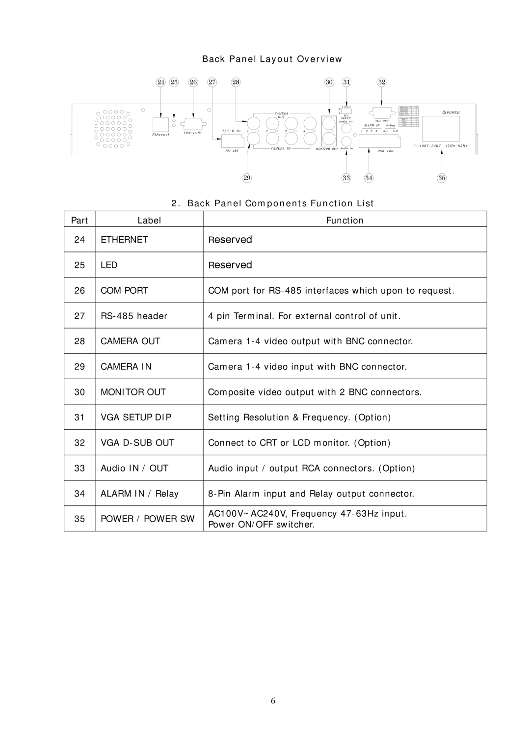
Back Panel Layout Overview
24 | 25 | 26 | 27 | 28 | 30 | 31 | 32 |
|
| 29 | 33 | 34 | 35 |
| 2. Back Panel Components Function List |
| |||
|
|
|
|
|
|
Part | Label |
| Function |
|
|
|
|
|
|
|
|
24 | ETHERNET | Reserved |
|
|
|
|
|
|
|
|
|
25 | LED | Reserved |
|
|
|
|
|
| |||
26 | COM PORT | COM port for | |||
|
|
|
| ||
27 | 4 pin Terminal. For external control of unit. |
| |||
|
|
|
| ||
28 | CAMERA OUT | Camera |
| ||
|
|
|
| ||
29 | CAMERA IN | Camera |
| ||
|
|
|
| ||
30 | MONITOR OUT | Composite video output with 2 BNC connectors. |
| ||
|
|
|
| ||
31 | VGA SETUP DIP | Setting Resolution & Frequency. (Option) |
| ||
|
|
|
| ||
32 | VGA | Connect to CRT or LCD monitor. (Option) |
| ||
|
|
|
| ||
33 | Audio IN / OUT | Audio input / output RCA connectors. (Option) |
| ||
|
|
|
| ||
34 | ALARM IN / Relay |
| |||
|
|
|
| ||
35 | POWER / POWER SW | AC100V~AC240V, Frequency |
| ||
Power ON/OFF switcher. |
|
|
| ||
|
|
|
|
| |
|
|
|
|
|
|
6
