SyncMaster 650MP-2, 650FP-2
LCD Display
User Manual
Safety Instructions
Power
Notational
Warning / Caution
Installation
Clean
Connecting a Computer
Connections
Others
Set a resolution and frequency appropriate to the product
When using headphones or earphones, do not turn the volume too high
This may result in a product malfunction, electric shock, or fire
Otherwise, this may result in an explosion or fire
When replacing the battery, insert it with the right polarity +
This reduces eye fatigue
The product may fall and cause personal injury or death
This may reduce the lifetime of the product, and may result in fire
Do not use a humidifier near the product
If a spark occurs, it may cause an explosion or fire
Otherwise, it may fall and result in personal injury
Package Contents
Checking the Contents of the Package
Introduction
Unpacking
Manuals
Cables
Others
Sold separately
Adjust buttons Left-Right buttons / Volume buttons
Your LCD Display Front
Ferrite Core
MENU button MENU
Power button
Power indicator
Remote Control Sensor
Rear
POWER S/W ON / OFF O
POWER
RS232C OUT/IN RS232C Serial PORT
RGB IN PC Connection Terminal In- put
DVI/RGB/HDMI AUDIO IN PC/DVI/ HDMI Audio Connection Terminal Input
AV/COMPONENT AUDIO IN R-AUDIO L
DVI OUT
AV IN VIDEO
Remote Control
BNC OUT R, G, B, H, V BNC Terminal Output
SBB Lcok
1. POWER 2. OFF 3. Number Buttons 4. DEL / GUIDE but- ton 5. - VOL +
POWER OFF Number Buttons DEL / GUIDE button - VOL + SOURCE D.MENU
Press the button to change the input signal SOURCE
6. SOURCE
DUAL
You can select MTS Multichannel Television Stereo mode
Mechanical Layout Mechanical Layout Installation VESA Bracket
Dimensions
Wall Bracket Installation
Wall Bracket Assembly
Components
Introduction There are two hingesleft and right. Use the correct one
Captive Screw
Wall Bracket
Hinge Left
To mount the product on the wall bracket
Wall Bracket Angle Adjustment
Introduction
Connections
Connecting to Other devices
Connecting AV Devices
Connecting to a Camcorder
Connecting the BNC to BNC cable
Connecting Using a DVI Cable
Connecting Using a HDMI Cable
Connecting Using a DVI to HDMI Cable
Connecting a DVD Player
Connecting a DTV Set Top Cable/Satellite Box
Connecting to an Audio System
MDC Multiple Display Control Installation
Installation Problems
Uninstall
Introduction
Main Screen
Port Selection
Safety Lock
Main Icons
Select Button
Power Control
Info Grid shows some basic information necessary to Power Control
1 Power Status 2 Input 3 Image Size 4 On Timer 5 Off Timer
Input Source
The Power Control feature is available for all displays
PC Mode
Image Size PC, BNC, DVI
Image Size TV, AV, S-Video, Component, DVIHDCP, HDMI, DTV
The Input source of MagicInfo works only on MagicInfo model
The Input source of TV works only on TV model
Time
The Auto Wide mode is available only for TV, AV, and S-Video
PIP PIP Size
At On Time Setup, TV Source functions only for TV Model
At On Time Setup, MagicInfo Source functions only for MagicInfo Model
PIP PIP Source
PIP Size can be controlled with turning on the LCD Display power
Settings
Picture
Settings Picture PC
Color Temp is only enabled if the Color Tone is set to Off
Settings Audio
Settings
Maintenance Lamp Control
Image Lock
Maintenance Scroll
Maintenance Video Wall
z The place will be set up by pressing a number in the selected mode
1 Video Wall
2 Video Wall Screen divider The screen can be divided into
z Select a display from Display Selection
Troubleshooting
Settings Value Display In Multiple Display Mode
You may not operate this function in MagicInfo
Page
Adjusting the LCD Display
Input Available Modes
Source List
PC / DVI / BNC AV Component HDMI MagicInfo
Source
Off On
Swap
Size
Position
Transparency
Edit Name
High Medium Low Opaque
Picture PC / DVI / BNC / MagicInfo Mode Available Modes
MagicBright
1. Entertain
2. Internet
Custom
4. Custom
1. Contrast
2. Brightness
Color Tone
Color Control
1. Off 2. Cool 3. Normal 4. Warm 5. Custom
1. Red
Color Temp
Image Lock
Coarse
Fine
Auto Adjustment
Signal Balance
Signal Control
1. R-Gain
2. G-Gain
3. B-Gain
HDMI Black Level
6. B-Offset
PIP Picture
1. Normal 2. Low
4. Color
Dynamic Contrast
Lamp Control
5. Tint
1. Off 2. On
Brightness Sensor
Picture AV / HDMI / Component Mode Available Modes
Mode
Contrast
Brightness
Dynamic, Standard, Movie, or Custom can be activated 1. Dynamic
2. Standard 3. Movie 4. Custom
Sharpness
Color
Tint
1. Off 2. Cool2
3. Cool1 4. Normal 5. Warm1 6. Warm2
Digital NR Digital Noise Reduction
Film Mode
Dynamic Contrast
Sound Available Modes
Bass
Treble
Balance
1. Standard
Auto Volume
SRS TS XT
Sound Select
Setup Available Modes
Speaker Select
1. Main 2. Sub
1. Internal
Language
Time
Clock Set
HDMI MagicInfo
Sleep Timer
On Timer
Off Timer
1. Off
Safety Lock Change PIN
Menu Transparency
1. High 2. Medium 3. Low 4. Opaque
Lock
Energy Saving
Video Wall
Format
Horizontal
1. Full
2. Natural
Safety Screen
Vertical
Screen Divider
Pixel Shift Pixel Shift
Timer Timer
1. Scroll
Period
Scroll
2. Bar 3. Eraser
Mode-Scroll 1~5 sec Mode-Bar, Eraser 10~50 sec
Resolution Select
Eraser
Side Gray
1. Off 2. Light 3. Dark
Power On Adjustment
1. Off 2. 1024 X 3. 1280 X 4. 1360 x 5. 1366 X
Reset
Image Reset
Color Reset
OSD Rotation
ID Setup
Multi Control Available Modes
Multi Control
ID Input
MagicInfo Available Modes
MagicInfo
Adjusting the LCD Display 3. Select Language - step
Shows the settings that have been selected by the user
Troubleshooting
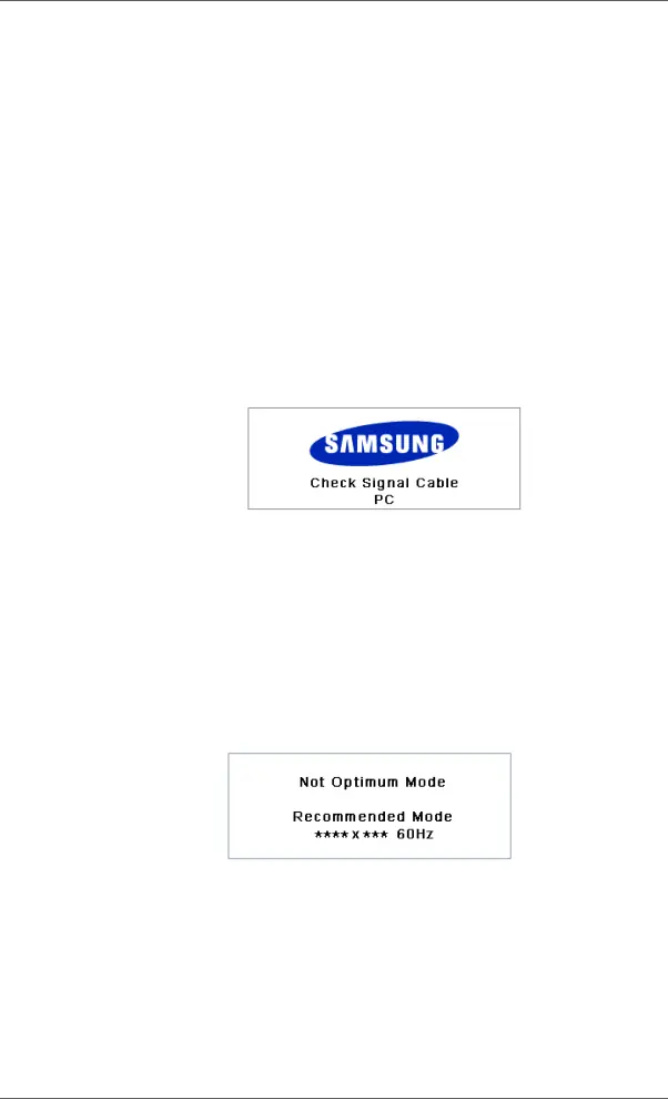
Self-Test Feature Check
Maintenance and Cleaning
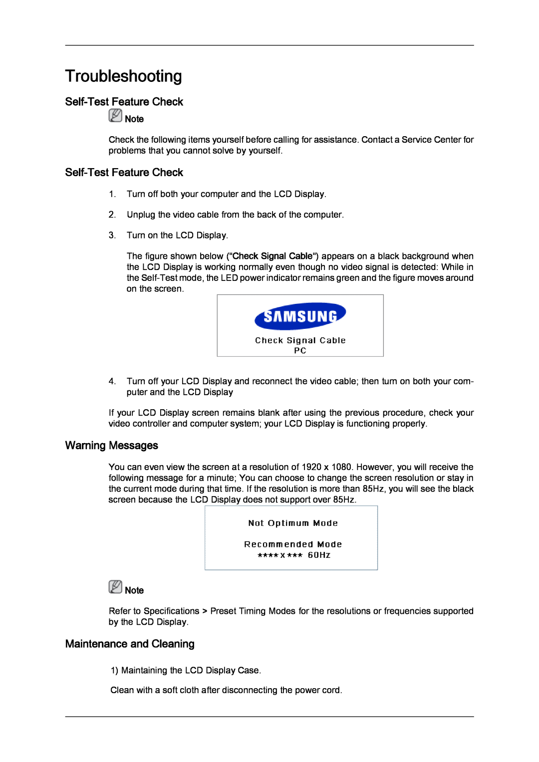
Warning Messages
Symptoms and Recommended Actions
Problems related to the Installation PC Mode
Check List
Problems related to the Screen
Q Check Signal Cable message
Q Not Optimum Mode message
Problems related to Audio
Problems related to the Remote Control
Q & A
Troubleshooting
Specifications
Resolution
Input Signal, Terminated
Power Supply
PowerSaver
VESA Mounting Interface
Environmental considerations
Plug and Play Capability
Preset Timing Modes
Horizontal Frequency
Vertical Frequency
What is Image Retention ?
Information
For a Better Display
PRODUCT INFORMATION Image Retention Free
Power Off, Screen Saver, or Power Save Mode
Change the Color Information periodically
Information
Change the characters color periodically
Apply the Screen Scroll function on Product
Apply the Screen Pixel function on Product
Apply the Screen Erasing function on Product
Symptom Horizontal / Vertical Bar with Black Color move up and down
Symptom 2 Vertical blocks move while erasing the display
Apply the Screen Bar function
Appendix
Contact SAMSUNG WORLDWIDE
North America
Latin America
Europe
Asia Pacific
Terms
Middle East
Africa
Correct Disposal
Authority
Correct disposal of batteries in this product - Europe only
Information in this document is subject to change without notice
Appendix