PREPARING THE INSTALLATION
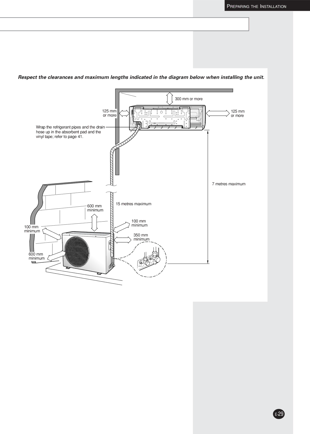
Respect the clearances and maximum lengths indicated in the diagram below when installing the unit.
| 300 mm or more |
125 mm | 125 mm |
or more | or more |
Wrap the refrigerant pipes and the drain |
|
hose up in the absorbent pad and the |
|
vinyl tape; refer to page 41.
7 metres maximum
600 mm | 15 metres maximum |
| |
minimum |
|
100 mm minimum
100 mm minimum
350 mm minimum
600 mm minimum
The designs of the unit and the connection valve are subject to change according to the model.
