C o n n e c t i o n s
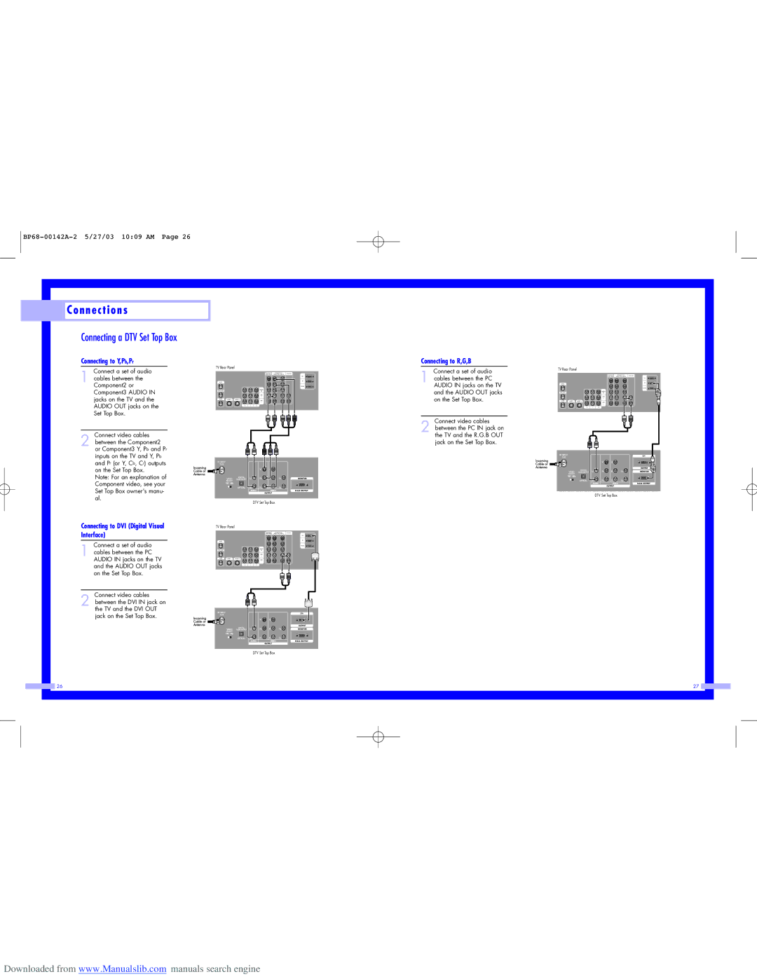
Connecting a DTV Set Top Box
Connecting to Y,Pb,Pr
Connect a set of audio
1 cables between the Component2 or Component3 AUDIO IN jacks on the TV and the AUDIO OUT jacks on the Set Top Box.
Connect video cables
2 between the Component2 or Component3 Y, Pb and Pr inputs on the TV and Y, Pb and Pr (or Y, Cb, Cr) outputs on the Set Top Box.
Note: For an explanation of Component video, see your Set Top Box owner's manu- al.
TV Rear Panel
ANT
|
|
|
|
|
| Connecting to R,G,B | |
|
|
| (480i/480p) | (480p/720p/10801i) | PC AUDIO | 1 | Connect a set of audio |
|
|
| Component1 | Component1/2 |
| cables between the PC | |
|
|
|
|
| PC | ||
|
|
|
|
| DVI |
| |
|
|
| Y |
|
|
| |
|
|
| P |
| AUDIO IN jacks on the TV | ||
|
| MONITOR | P |
|
|
| and the AUDIO OUT jacks |
|
| VIDEO |
|
|
| ||
|
| OUT |
|
|
|
| |
|
| 2 | L |
| L |
| on the Set Top Box. |
|
| VIDEO1 | R |
| R |
| |
V | L | R |
|
|
|
|
|
|
|
|
|
|
|
| Connect video cables |
|
|
|
|
|
| 2 between the PC IN jack on | |
|
|
|
|
|
|
| the TV and the R.G.B OUT |
|
|
|
|
|
|
| jack on the Set Top Box. |
DTV Set Top Box
TV Rear Panel
|
| Component1 | Component1/2 | PC AUDIO |
|
| (480i/480p) | (480p/720p/10801i) | |
|
|
|
| DVI |
|
| Y |
| PC |
|
|
| ||
|
| P |
| |
ANT | MONITOR | P |
|
|
OUT |
|
| ||
| VIDEO |
|
|
|
| 2 | L |
| L |
|
| |||
|
| VIDEO |
|
|
|
| 1 | R | R |
V | L |
| R | ||
|
|
|
|
|
|
|
|
|
|
|
|
|
|
|
|
|
|
DVI
DTV Set Top Box
Connecting to DVI (Digital Visual | TV Rear Panel |
|
|
|
|
|
| ||
Interface) |
|
|
|
|
| Y | Component1/2 |
| |
|
|
|
|
|
|
| Component1 | PC AUDIO | |
|
|
|
|
|
|
| (480i/480p) | (480p/720p/10801i) | |
|
|
|
|
|
|
|
|
| DVI |
1 |
|
|
|
|
|
|
| PC | |
Connect a set of audio |
|
|
|
| MONITOR | P |
| ||
cables between the PC | ANT |
|
|
| VIDEO | P |
|
| |
|
|
|
| OUT |
|
| |||
AUDIO IN jacks on the TV |
| VIDEO2 | L |
| L | ||||
|
|
|
|
| 1 | R |
| R | |
| and the AUDIO OUT jacks |
|
| V | L | R |
|
|
|
| on the Set Top Box. |
|
|
|
|
|
|
|
|
Connect video cables |
|
2 between the DVI IN jack on |
|
the TV and the DVI OUT |
|
jack on the Set Top Box. | DVI |
| |
| DTV Set Top Box |
26
27 |
Downloaded from www.Manualslib.com manuals search engine