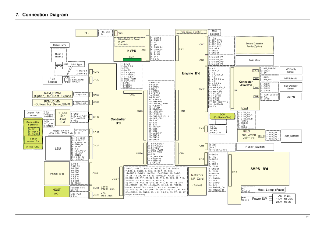
Samsung ML-1651N, ML-1650 specifications Connection Diagram, Vps

Models: ML-1650 ML-1651N

1 67
Download 67 pages 54.48 Kb
Page 67
Image 67

7. Connection Diagram


PT L

PTL Ct rl


CN 3


Feed Sensor is on B’d


5V


Micro Switch on Board


1

- GN D _5


2

- GN D _5


In-24V


3 -

5 V


Thermistor


Out-24VS


4 -

5 V


C N 7


5

- GN D _2 4


CN 1


H VPS

CN1


6

- GN D _2 4


7 -

2 4 V S


Therm 1


8

-

2 4 V S


Therm 2


CN 2


9 -

2 4 V


1

0- 2 4V


CN 8


Joint type


1 - 2 4 V S


2 - GN D _2 4


Main

Solenoid

1 - + 5 V

2 - SC F _ST S

3 - SC F _CM D

4 - SC F _CL K

5 - SC F _RD Y

6 - + 2 4V S

7 - GN D 5

8 - GN D 24

1 - M ot or 1 _PA

2 - M ot or 1 _PA *

3 - M ot or 1 _PB*

4 - M ot or 1 _PB

Second Cassette

Feeder(Option)

Main Motor


3

- 5 V S


1 -Therm 1


CN 2 4

4

- GN D 5


Engine

B’d


2 -The r m 2


5 - T H V _P WM


6

- T H V REA D


Exit


1 - 5V


7

- T H V _E N *


2 - Ex i t_sig nal


CN 2 2

8

- M H V _PW M


Sensor


3 - GN D _5


9

- D E V _PW M

1

- R EA D Y*


1

0- PT L


1 1- GN D 5

2 - n EB SY


1 2- GN D 5

3 - n EM SG

CN 17


4

- C C L K


5

- n CM SG


RAM_DIMM


100pin slot


6

- n F SYN C


(Opt ion) for

RAM_Expand


CN 29


CN 20

7

- n PRIN T


8

- L SY N C *


9

- T H ERM 1


ROM_DIMM


100pin slot


CN 28


1

0- T H E RM 2


(Option) f or

Demo_SIMM


1

1- C OV ER_OPEN


1 - N .C

2 - F A N _J

3 - N .C

4 - M P_SOL _J

5 - N .C

6 - M T R_EN _A 7 - N .C

8 - M T R_PA

9 - SIZ E 1_J

1 0- M T R _E N _B

1 1- SIZ E2 _J

1 2- M T R _P B

1 3- SIZ E3 _J

1 4- + 24 V S

1 5- D GN D

1 6- A GN D

1 7- M P _E M PT Y_J 1 8,19 - D GN D

C N7

CN5

Connector

Joint B’d

CN6

CN 1

CN4

1

- MP_EM PTY*

2

- GND 5

3

- 5V

1

- 24VS

2

- MP_SOL

1

- SIZ E 1

2

- SIZ E 2

3

- SIZ E 3

4

- GN D 5

1

- F A N Con tr o l

2

- N.C .

3

- 24 V S

MP Empty

Sensor

MP Solenoid

Size Detector

Sensor

DC FAN


1 2

- P_EX IT *


1 3

- L D ON *


CN 25

1 4

- PM OT OR *

CN 6

2 0- 5 V

CN2

Output

Full

1 - 5V

T _sen

1 - GN D


1 5- L RE A DY *


2 - Signal


1 6

- L SU C L K


sensor

3 - G N D 5

sor

2 - Ou tpu t_F ul l *


CN 19


1 7

- OU T PU T _F U L L *


Joint

3 - T _SN E SOR


Controller

1 8

- D ET _C RU


C onnect ion

1 - 5V

B’d

4 - V C C


B’d


1 9- 3 .3 V


2 - T _s en


2 0

- 3 .3 V


T erm inal


2 1

- 3 .3 V


3 - G N D 5


2 2

- V ID EO*


CN 5


1 - 5V


M icr o - Sw it c h


1 - L SU _5V


2 3

- V C C


2 - s ignal


CN 23


2 4

- V C C


(For

L SU 5V S C ut)

2 - 5V


2 5

- nV ID E O*


3 - G N D 5


2 6

- GN D 5


T oner


1 - L SU _C L K


2 7

- GN D 5


2 8

- GN D 5


sens or

B ’d


2 - L R EA D Y*


3 - P _M OT OR*


1 - T H V _P WM *


DCU

(For System Test)

1 - 5 V

2 - R XD

3 - T X D

4 - GN D - 5 V

1 - M T R_PA

2 - M T R_EN _A

3 - M T R_PB

4 - M T R_EN _B

5 - + 2 4V S

6 - GN D 24 7 - + 5 V

8 - GN D 5

CN 2

SUB_MOTOR CN 1 JOINT B’D

1- MT R_PA

2- MT R_PA *

3- MT R_PB

4 - MT R_PB *

SUB_MOTOR


4

- GN D _2 4


CN 21


2 - T H V _R EA D


CN 6

i n t h e CRU


LSU

5

- 2 4 V S


3

- T H V EN *


6

- N .C


7

- L SU _V D O*


4

- M H V _PW M


5

- D E V _PW M


8 - L D _ON *


C N 26


CN 4


9

- GN D 5


6

- P T L


7

- T _SEN SOR


1

0- L SU _5V


8

- R eser ved


CN 2


1

1- H SYN C*


9

- R eser ved


1

- V C C


1

0- GN D 2 4


2

- GN D 5


3

- L E D 1


1 - N .C ,. 2 - N .C., 3- 5 V , 4 - /IOC S3, 5- D 3 1,

6- D 3 0,


4

- L E D 2


1 - 2 4 v 2 - N .C

3 - F U SER_2 4V S

1 - GN D 5

2 - + 5 V

3 - GN D 5

4 - + 5 V

5 - GN D 5

6 - + 3 .3V

7 - GN D 24

Fuser _Swit ch

SMPS B’d


5 - L E D 3


7 - D 2 9, 8- GN D5 , 9 - D 28 , 1 0 - D 2 7, 11 - D 26 ,


Panel B’d


CN 18


1 2

- GN D 5 ,1 3 - D 2 5, 1 4- D 24 , 1 5 - / EIR Q1,

16 - GN D 5,


6 - L E D 4


Net wor k


7 - K E Y1


1 7

- A 5 , 1 8- A 4, 1 9- A 3, 20 - /E IRQ0 ,2 1 - A 2 ,22 - D 23 ,


2 3- D 22 , 2 4 - A1 7 , 2 5- D 2 1, 26 - A1 6 , 2 7- D 2 0, 28 - A 15 ,

I /F Car d


8 - K E Y2


CN 2 7


2 9- D 19 , 3 0 - A1 4 , 3 1- D 1 8, 32 - A1 3 ,


9 - L E D 5


1 0- K EY 3


3 3- D 17 , 3 4 - A1 2 , 3 5- D 1 6, 36 - A1 1 , 3 7- A 6 , 3 8- A 1 0,

(Option)


36Pin

3 9

- / RESET , 40 - A 9,

41 - /W A IT , 42 - A 8,

43 - /IOC S3,


Par al l el Por t


CN 30

4 4

- A 7 , 4 5- / IOCS3 ,

4 6- N .C ., 4 7- N .C .,

48 - GN D 5 ,


HOST


P1284 Con .


3 6 Pi n


4 9- A 1 8, 50 - /RD , 51 - /W E, 52 - GN D 5 ,

5 3- N .C .,

5 4- N .C .,


(PC )

U SB P or t


4Pin

5 5

- / EIRQ1 , 5 6- GN D 5 , 5 7- N .C ., 5 8- 5 V ,

5 9- 5 V ,

6 0 - 5 V


CN 31


( 60 pi n Co nn ect or )


4 Pi n


U SB Jac k


8 - + 3 .3V 9 - GN D 24 1 0- 2 4V

1 1- GN D 2 4

1 2- 2 4V

1 3- GN D 2 4

1 4- 2 4V

1 5- F U SE R_ON

1 6- F U SE R_24

CN 3

02

01

H OT

N e utr a l

H OT

N e utr al

Heat Lamp (Fuser)


AC

In-Let

Power SW


110V

for USA


220V

for EU


7-1

Page 67
Image 67
Samsung ML-1651N, ML-1650 specifications Connection Diagram, Vps

ML-1650, ML-1651N specifications

The Samsung ML-1651N and ML-1650 are reliable monochrome laser printers designed for small to medium-sized businesses and home offices. These printers offer a blend of performance, efficiency, and affordability, making them suitable for various printing needs.

One of the standout features of both models is their print speed. The ML-1651N boasts a speed of up to 22 pages per minute, while the ML-1650 offers a slightly lower speed but still impressive for standard office tasks. This fast output is complemented by a first page print time of approximately 8.5 seconds, ensuring that users can quickly produce documents without unnecessary delays.

In terms of print quality, both printers deliver sharp, clear black text and detailed graphics, thanks to a print resolution of up to 1200 x 1200 dpi. This high resolution is essential for producing professional-looking documents, which is crucial in a business environment.

The Samsung ML-1651N and ML-1650 are equipped with a 250-sheet input tray, accommodating various paper sizes and types. Additionally, both printers support manual duplex printing, allowing users to save paper by printing on both sides of the page. The ML-1651N also features a built-in network interface, providing easy connectivity for multiple users on a local network. This is particularly beneficial for businesses where collaboration and document sharing are essential.

Another noteworthy characteristic is their energy efficiency. Both models comply with Energy Star standards, reducing electricity consumption and helping organizations lower their operational costs. The Eco Mode feature further enhances sustainability by optimizing power usage during printing tasks.

The compact size of the ML-1651N and ML-1650 makes them suitable for smaller workspaces where printer footprint is a consideration. Despite their size, they have a robust build quality, ensuring longevity and reliability in daily use.

Lastly, both models are compatible with various operating systems, including Windows and Mac, ensuring versatility in different computing environments. With their blend of speed, efficiency, and quality, the Samsung ML-1651N and ML-1650 remain solid contenders in the monochrome laser printer market. They are ideal choices for users seeking reliable, cost-effective solutions for their printing requirements.