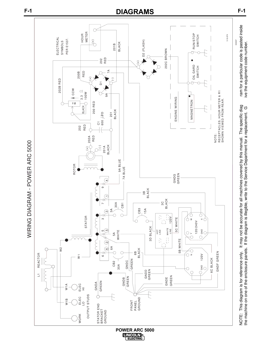
WIRING DIAGRAM - POWER ARC 5000
| W1B |
WORK | ELEC |
| LO |
OUTPUT STUDS
L1 REACTOR
W2
W1A |
|
|
ELEC | W | 1 |
|
| |
HI |
| STATOR |
|
|
ROTOR
(+)
202A
202
RED
R1
BLACK
202B RED
CCW
200B
3.3
RED
100W
![]() (+)
(+)
ELECTRICAL
SYMBOLS
PER E1537.
HOUR
METER
![]() POWER ARC 5000
POWER ARC 5000
STATOR END BRACKET GROUND
FRONT
PANEL
GROUND
GNDA |
|
|
|
|
GREEN | 6 |
| 5 | 3 |
|
| |||
| 6 | 2 | 5 |
|
| 6A |
|
|
|
| CB2 |
| 5A |
|
| 30A | WHITE |
| |
GNDB |
|
|
|
|
GREEN | GNDC |
|
|
|
|
|
|
| |
| GREEN |
|
|
|
| 6B |
|
|
|
| BLACK |
|
|
|
GNDD |
|
|
|
|
GREEN |
| 3D | BLACK |
|
|
|
| ||
RED
|
|
|
| |
| 7 | 9 |
| 201A |
3 | 1 |
| 4 | |
| BLACK | |||
|
|
|
| |
3A |
|
|
|
|
| 30A |
|
|
|
|
|
|
| 9A BLUE |
| CB1 |
|
| 7A BLUE |
|
|
|
|
CB3
15A 3B BLACK
200 RED
C1
![]() 600
600 ![]()
![]() FD
FD
201 BLACK
D1
9A
7A
![]()
(+)
202 RED
201B
BLACK
![]() (+)
(+)
D2 (FLASH)
DIAGRAMS
|
| HOT |
|
|
| LINE | 3C |
|
|
| |
GNDE |
| WHITE | BLACK |
|
|
| |
GREEN |
| LINE | 120V |
|
| 5C | GNDG |
|
| WHITE | |
| 5B | WHITE | GREEN |
|
| ||
| N | Y | W |
|
| 120/240V | |
GND | 120V | GND | X |
ENGINE WIRING
R
MAGNETRON
202C BROWN
OIL GARD | R |
RUN/STOP | |
SWITCH | SWITCH |
6C BLACK
NOTE:
GNDF GREEN
RECEPTACLES, HOUR METER & R1
SHOWN VIEWED FROM REAR.
S22257
NOTE: This diagram is for reference only. It may not be accurate for all machines covered by this manual. The specific diagram for a particular code is pasted inside the machine on one of the enclosure panels. If the diagram is illegible, write to the Service Department for a replacement. Give the equipment code number.