| TROUBLESHOOTING | |||
|
|
|
|
|
| Observe all Safety Guidelines detailed throughout this manual | |||
|
|
|
|
|
| PROBLEMS | POSSIBLE AREAS OF | RECOMMENDED | |
| (SYMPTOMS) | MISADJUSTMENTS(S) | COURSE OF ACTION |
|
|
|
|
|
|
PROBLEMS
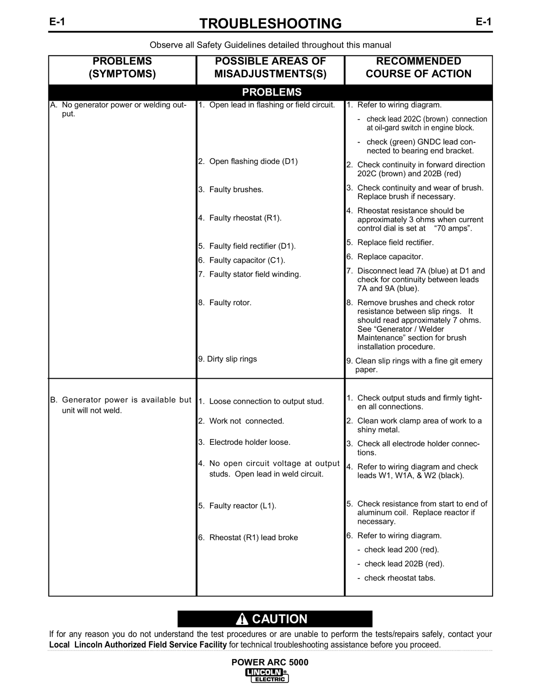
A.No generator power or welding out- 1. Open lead in flashing or field circuit. 1. Refer to wiring diagram. put.
-check lead 202C (brown) connection at
-check (green) GNDC lead con- nected to bearing end bracket.
2. | Open flashing diode (D1) | 2. | Check continuity in forward direction | |
|
|
| 202C (brown) and 202B (red) | |
3. | Faulty brushes. | 3. | Check continuity and wear of brush. | |
|
|
| Replace brush if necessary. | |
4. | Faulty rheostat (R1). | 4. | Rheostat resistance should be | |
| approximately 3 ohms when current | |||
|
|
| control dial is set at “70 amps”. | |
5. | Faulty field rectifier (D1). | 5. | Replace field rectifier. | |
|
|
| ||
6. | Faulty capacitor (C1). | 6. | Replace capacitor. | |
|
|
| ||
7. | Faulty stator field winding. | 7. | Disconnect lead 7A (blue) at D1 and | |
| check for continuity between leads | |||
|
|
| ||
|
|
| 7A and 9A (blue). | |
8. | Faulty rotor. | 8. | Remove brushes and check rotor | |
|
|
| resistance between slip rings. It | |
|
|
| should read approximately 7 ohms. | |
|
|
| See “Generator / Welder | |
|
|
| Maintenance” section for brush | |
|
|
| installation procedure. | |
9. Dirty slip rings | 9. Clean slip rings with a fine git emery | |||
|
|
| paper. | |
|
|
|
| |
B. Generator power is available but 1. | Loose connection to output stud. | 1. | Check output studs and firmly tight- | |
unit will not weld. |
|
| en all connections. | |
| 2. | Clean work clamp area of work to a | ||
2. | Work not connected. | |||
|
|
| shiny metal. | |
3. | Electrode holder loose. | 3. | Check all electrode holder connec- | |
|
|
| tions. | |
4. | No open circuit voltage at output | 4. | Refer to wiring diagram and check | |
| studs. Open lead in weld circuit. |
| leads W1, W1A, & W2 (black). | |
5. | Faulty reactor (L1). | 5. | Check resistance from start to end of | |
|
|
| aluminum coil. Replace reactor if | |
|
|
| necessary. | |
6. | Rheostat (R1) lead broke | 6. | Refer to wiring diagram. | |
|
|
| - | check lead 200 (red). |
|
|
| - | check lead 202B (red). |
|
|
| - | check rheostat tabs. |
![]() CAUTION
CAUTION
If for any reason you do not understand the test procedures or are unable to perform the tests/repairs safely, contact your Local Lincoln Authorized Field Service Facility for technical troubleshooting assistance before you proceed.
POWER ARC 5000
