OPERATION | ||
|
|
|
CONTROLS AND SETTINGS
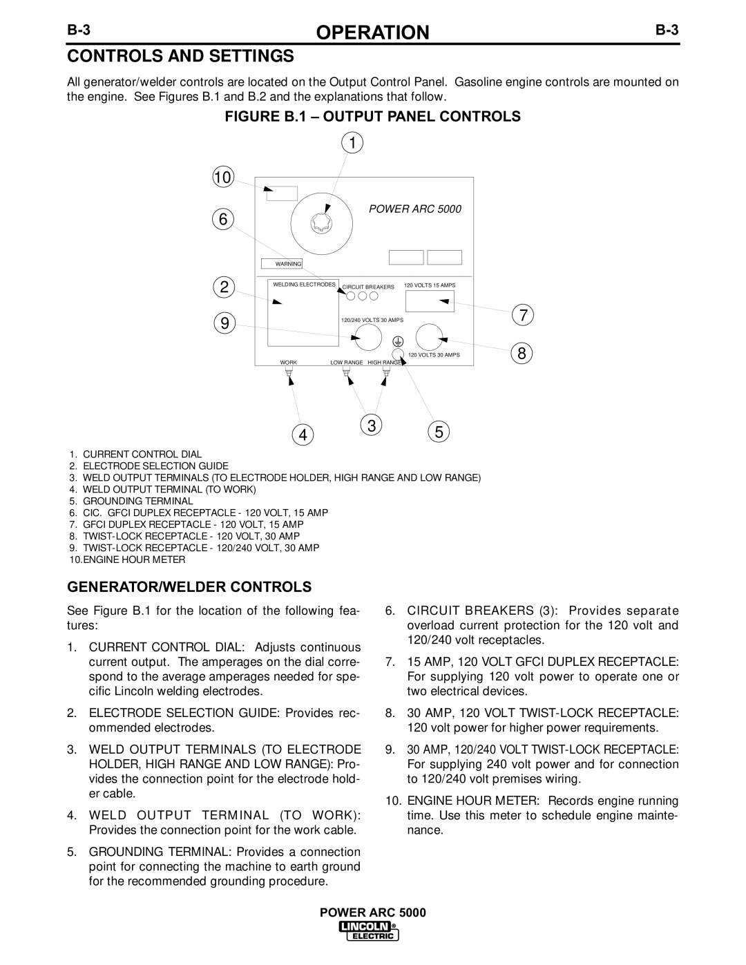
All generator/welder controls are located on the Output Control Panel. Gasoline engine controls are mounted on the engine. See Figures B.1 and B.2 and the explanations that follow.
FIGURE B.1 – OUTPUT PANEL CONTROLS
1
10
POWER ARC 5000
6
WARNING
2 | WELDING ELECTRODES | CIRCUIT BREAKERS | 120 VOLTS 15 AMPS | ||
|
|
|
| ||
9 |
|
| 120/240 VOLTS 30 AMPS |
| |
|
|
|
|
| 120 VOLTS 30 AMPS |
| WORK | LOW RANGE | HIGH RANGE |
| |
4 3 5
1.CURRENT CONTROL DIAL
2.ELECTRODE SELECTION GUIDE
3.WELD OUTPUT TERMINALS (TO ELECTRODE HOLDER, HIGH RANGE AND LOW RANGE)
4.WELD OUTPUT TERMINAL (TO WORK)
5.GROUNDING TERMINAL
6.CIC. GFCI DUPLEX RECEPTACLE - 120 VOLT, 15 AMP
7.GFCI DUPLEX RECEPTACLE - 120 VOLT, 15 AMP
8.
9.
10.ENGINE HOUR METER
7
8
GENERATOR/WELDER CONTROLS
See Figure B.1 for the location of the following fea- tures:
1.CURRENT CONTROL DIAL: Adjusts continuous current output. The amperages on the dial corre- spond to the average amperages needed for spe- cific Lincoln welding electrodes.
2.ELECTRODE SELECTION GUIDE: Provides rec- ommended electrodes.
3.WELD OUTPUT TERMINALS (TO ELECTRODE HOLDER, HIGH RANGE AND LOW RANGE): Pro- vides the connection point for the electrode hold- er cable.
4.WELD OUTPUT TERMINAL (TO WORK): Provides the connection point for the work cable.
5.GROUNDING TERMINAL: Provides a connection point for connecting the machine to earth ground for the recommended grounding procedure.
6.CIRCUIT BREAKERS (3): Provides separate overload current protection for the 120 volt and 120/240 volt receptacles.
7.15 AMP, 120 VOLT GFCI DUPLEX RECEPTACLE: For supplying 120 volt power to operate one or two electrical devices.
8.30 AMP, 120 VOLT TWIST-LOCK RECEPTACLE:
120 volt power for higher power requirements.
9.30 AMP, 120/240 VOLT
10.ENGINE HOUR METER: Records engine running time. Use this meter to schedule engine mainte- nance.
POWER ARC 5000
