INSTALLATION | ||
|
|
|
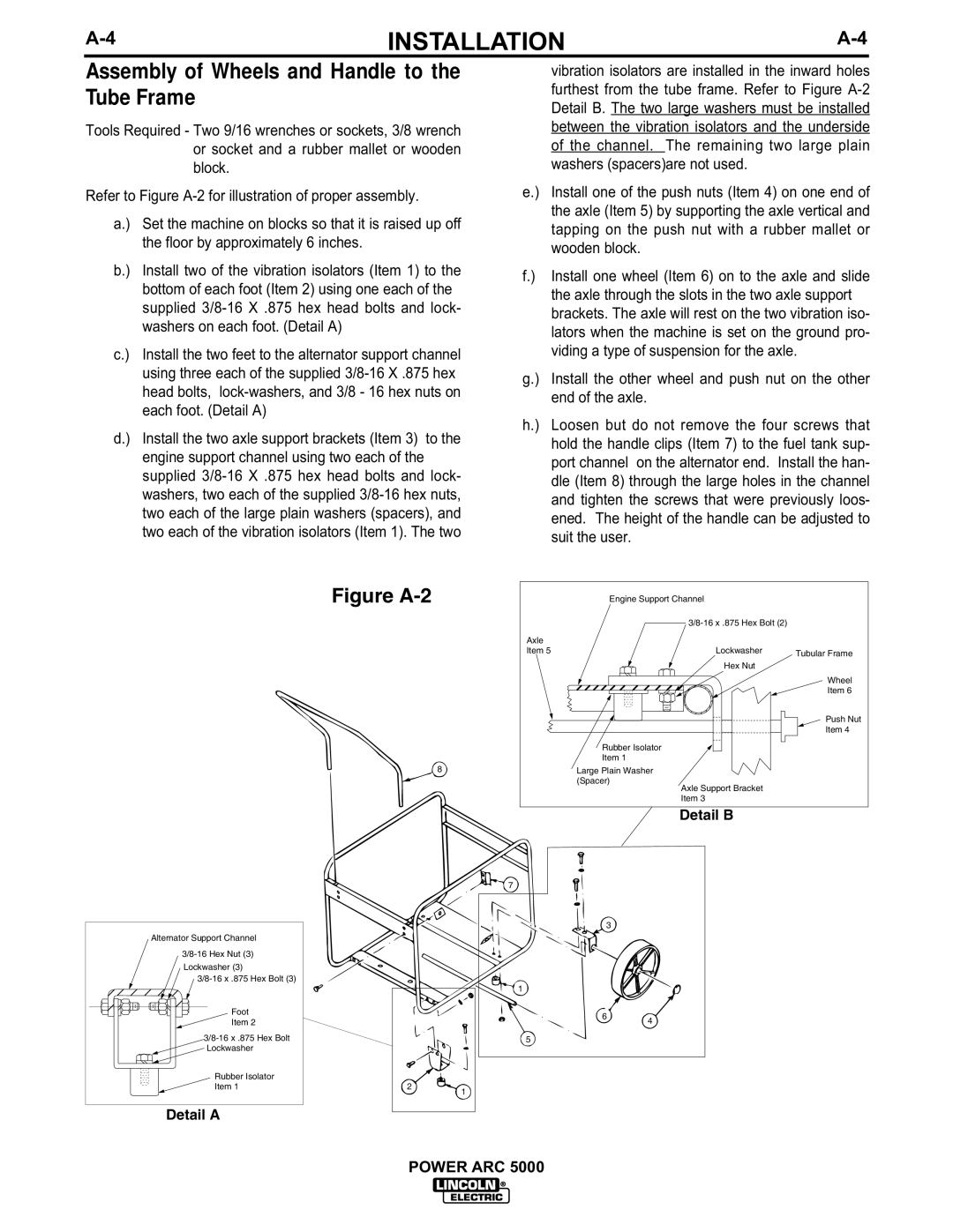
Assembly of Wheels and Handle to the Tube Frame
Tools Required - Two 9/16 wrenches or sockets, 3/8 wrench or socket and a rubber mallet or wooden block.
Refer to Figure
a.) | Set the machine on blocks so that it is raised up off |
| the floor by approximately 6 inches. |
b.) | Install two of the vibration isolators (Item 1) to the |
| bottom of each foot (Item 2) using one each of the |
| supplied |
| washers on each foot. (Detail A) |
c.) | Install the two feet to the alternator support channel |
| using three each of the supplied |
| head bolts, |
| each foot. (Detail A) |
d.) | Install the two axle support brackets (Item 3) to the |
| engine support channel using two each of the |
| supplied |
| washers, two each of the supplied |
| two each of the large plain washers (spacers), and |
| two each of the vibration isolators (Item 1). The two |
Figure A-2
8
Alternator Support Channel
Lockwasher (3)
Foot
Item 2
Lockwasher
Rubber Isolator |
|
|
Item 1 | 2 | 1 |
|
|
Detail A
vibration isolators are installed in the inward holes furthest from the tube frame. Refer to Figure
e.) Install one of the push nuts (Item 4) on one end of the axle (Item 5) by supporting the axle vertical and tapping on the push nut with a rubber mallet or wooden block.
f.) Install one wheel (Item 6) on to the axle and slide the axle through the slots in the two axle support brackets. The axle will rest on the two vibration iso- lators when the machine is set on the ground pro- viding a type of suspension for the axle.
g.) Install the other wheel and push nut on the other end of the axle.
h.) Loosen but do not remove the four screws that hold the handle clips (Item 7) to the fuel tank sup- port channel on the alternator end. Install the han- dle (Item 8) through the large holes in the channel and tighten the screws that were previously loos- ened. The height of the handle can be adjusted to suit the user.
| Engine Support Channel |
|
|
| |
Axle |
|
|
Item 5 | Lockwasher | Tubular Frame |
|
| |
| Hex Nut |
|
|
| Wheel |
|
| Item 6 |
|
| Push Nut |
|
| Item 4 |
Rubber Isolator
Item 1
Large Plain Washer
(Spacer)
Axle Support Bracket Item 3
Detail B
7
3
1
6 4
5
POWER ARC 5000