Manuals
/
Samsung
/
Computer Equipment
/
Printer
Samsung
ML-1700
specifications
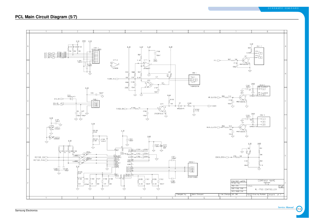
PCL Main Circuit Diagram 5/7
Models:
ML-1700
1
109
120
120
Download
120 pages
49.52 Kb
106
107
108
109
110
111
112
113
Troubleshooting
Specs
Parts list
Error messages
SPGPm Internal Block Diagram
All LEDs blinking Fuser Error
Self Diagnostic Mode
DCU Setup
Unit Assembly
Printing a cleaning sheet
Page 109
Image 109
S C H E M ATIC DIAG R A M S
PCL Main Circuit Diagram (5/7)
Service Manual
Samsung Electronics
11-5
Page 108
Page 110
Page 109
Image 109
Page 108
Page 110
Contents
Specifications
Precautions
Troubleshooting
Block Diagram
Electronics
2003
Precautions
Precaution related electric shock or fire
Precaution related noxious material
Precaution when assembly/disassembly
Precaution related handling the machine
ESD Precautions
DCUDiagnostic Control Unit Driver
Tool for Troubleshooting
LSU
Acronyms and Abbreviations
1 A4 5% Pattern
Sample Pattern for the Test
2 A4 2% Pattern
3 A4 IDC Pattern
Samsung Electronics
General Specifications
Specifications
Electrical Specification
Controller Specification
Environmental Range
Toner Cartridge Developer
Paper Handling Specifications
Specifications
Front View
Printer Components
Inside View
Rear View
Control Panel
On Line/Error and Toner Save LEDs
Printing demo
Cancel button
Fuser
System Layout
Transfer Ass’y
Feeding Part
Driver Ass’y
Fixing PartFuser
LSU Laser Scanner Unit
Safety Relevant Facts
Toner Cartridge
Main Pbaspl Model
Flash Memory
Asic Jupiter
Sdram
Sensor input circuit
Paper Exit Sensing
Paper Feeding, Toner Cartridge Sensing
Cover Open Sensing
DC FAN / Solenoid Driving
Sdram Regulator Clock Generator Buffer Motor Drive
Main PBA PCL Model
ML-1710 ML-1510 ML-1750
Memory
AsicSPGPm
AHB BUS
SPGPm Internal Block Diagram
Smps & Hvps
HVPSHigh Voltage Power Supply
Rated Power Output
SMPSSwitching Mode Power Supply
Consumption Power
Length of Power Cord 1830 ± 50mm Power Switch Use
Fuser AC Power Control
Drive
Engine F/W
Transfer
Feeding
Heat Lamp Method
Fusing
PID Method
5 LSU
What is the Q-PID Method?
Releasing Plastic Latches
General Precautions on Disassembly
Whenever servicing the machine, you must perform as follows
Top Cover
FuserHeat Lamp Type
Fuser
FuserQ-PID Type
Unplug Thermister Harness from the Fuser cover
LSU
Exit Roller
Driver Ass’y
Fan
Main PBA
Engine Shield Ass’y
Smps
Transfer Roller
Feed Roller
Pick Up Roller & Solenoid
DCU Setup
How to use DCU
Code
Error Code
Normal Code
Code Description
Self Diagnostic Mode
13 THV+ TRIGGER. ALL HV
Functi on Enter Up/ Dow n Stop Remar k
Self Test Button
Paper OutFace Up
Paper Path
Paper Exit Area JAM2
Clearing Paper Jams
Around the Toner Cartridge JAM1
Paper Feed Area JAM0
Tips for Avoiding Paper Jams
Printing a Demo
Sample Pattern
Printing a cleaning sheet
LED Status Display by Each Error
Consumables and Replacement Parts
Roller Defective image Typical defect
Periodic Defective Image
Samsung Electronics
Vertical Black Line and Band
Bad image
Vertical White Line
Black/White Spot
Horizontal Black Band
Dark Image or a Black
Light Image
Background
Uneven Density
Ghost
Satins on the Face
Blank Page Print out
Satins on Back
Wrong Print Position
Bad discharge
2 JAM
4 JAM
3 JAM
Paper rolled in the Fuser
Multi-Feeding
Paper rolled in the Toner Cartridge OPC Drum
All LEDs blinking Scan Error
All LEDs blinking Fuser Error
Malfunction
Paper Empty
Not function of the gear of the fuser due to melting away
Paper Empty without indication
Cover Open
No lamp on when the cover is open
Defective motor operation
No Power
Vertical Line Getting Curved
Precautions on Safe-keeping of Toner Cartridge
Toner Cartridge Service
Service for the Life of Toner Cartridge
Redistributing Toner
Image
Signs and Measures at Poor toner cartridge
Fault Signs Cause & Check Solution White Black spot
Printer is not working
Bad Environment of The Software
Utilities program
Abnormal Printing
How to delete the data in the spool manager
Spool Error
Exploded Views and Parts List
11-1 11-2 11-3
Main Assembly Parts List
Unit Assembly
Frame Unit Assembly Parts List
Frame Unit Assembly Parts ListCont
Drive Unit Assembly Parts List
Drive Unit Assembly
Cassette Unit Assembly
Cassette Unit Assembly Parts List
Fuser Unit Assembly
Fuser Unit Assembly Parts List
Samsung Electronics
9Block Diagram 9.1 PCL Model
Motor DR PART’S
SPL Model
PCL Model
Connection Diagram
Computer
PCL Main Circuit Diagram 1/7
Schematic Diagrams
PCL Main Circuit Diagram 2/7
PCL Main Circuit Diagram 3/7
PCL Main Circuit Diagram 4/7
PCL Main Circuit Diagram 5/7
PCL Main Circuit Diagram 6/7
PCL Main Circuit Diagram 7/7
SPL Main Circuit Diagram 1/5
SPL Main Circuit Diagram 2/5
SPL Main Circuit Diagram 3/5
SPL Main Circuit Diagram 4/5
SPL Main Circuit Diagram 5/5
THV
Hvps Circuit Diagram 1/2
4KV
Hvps Circuit Diagram 2/2
Smps Circuit Diagram 110V 1/2
CON2-14MANUAL CON2-25EXIT
Smps Circuit Diagram 110V 2/2
Top
Page
Image
Contents