Connecting to an External Source
![]() B
B
The auxiliary input can be used to take advantage of the sound quality of your
Examples: ![]() A television
A television
![]() A video disc player
A video disc player
![]() A
A
![]() To connect the external source, the source must have an audio output. In addition, you need an RCA connection cable.
To connect the external source, the source must have an audio output. In addition, you need an RCA connection cable.
1 | Set the system to standby mode and disconnect it and the external | |||
| source from the main. | |||
2 | Connect the audio cable to the rear of the | |||
| Connect the... | To the connector marked... | ||
| Red jack | R (right) | ||
| White jack | L (left) | ||
|
| For optimum sound quality, do not invert the right and left | ||
|
| channels. |
| |
3 | Plug the system back into the main socket and press On/Standby | |||
4 | ( |
| ) to switch it on. | |
Select the AUX source by pressing AUX. | ||||
| Result: AUX is displayed. | |||
5 | Switch the external source on. | |||
6 | Adjust the volume and balance as required: | |||
|
| Volume | Equalizer | |
Example: You can watch a film and take advantage of stereo sound provided that the original sound track is in stereo (as if you were in a cinema).
|
| Volume |
|
|
| EQ | S.Bass |
TUNER | CD | TAPE |
|
|
| AUX |
|
Band |
|
|
|
|
| Power |
|
|
| Sound |
|
Down | Tuning Mode | Up |
|
Speaker Connection
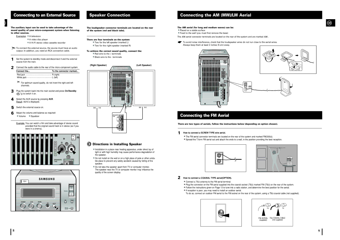
The loudspeaker connector terminals are located on the rear of the system (red and black tabs).
There are four terminals on the system:
![]() Two for the left speaker (marked L)
Two for the left speaker (marked L)
![]() Two for the right speaker (marked R)
Two for the right speaker (marked R)
To achieve the correct sound quality, connect the:
![]() Red wire to the + terminals
Red wire to the + terminals
![]() Black wire to the - terminals
Black wire to the - terminals
(Right Speaker) | (Left Speaker) |
| ANTENNA |
AC CORD
Directions in Installing Speaker
![]() Installation in a place near heating apparatus, under direct lay of light or with high humidity may cause performance degradation of the speaker.
Installation in a place near heating apparatus, under direct lay of light or with high humidity may cause performance degradation of the speaker.
![]() Do not install on the wall or on a high place of pole or other unsta- ble place to prevent any safety accident caused by falling of the speaker.
Do not install on the wall or on a high place of pole or other unsta- ble place to prevent any safety accident caused by falling of the speaker.
![]() Do not take the speaker apart from TV or computer monitor. The speaker near the TV or computer monitor may influence the quality of the screen display.
Do not take the speaker apart from TV or computer monitor. The speaker near the TV or computer monitor may influence the quality of the screen display.
Connecting the AM (MW)/LW Aerial
GB
The AM aerial (for long and medium waves) can be:
![]() Placed on a stable surface
Placed on a stable surface
![]() Fixed to the wall (you must first remove the base)
Fixed to the wall (you must first remove the base)
The AM aerial connector terminals are located on the rear of the system and are marked AM .
To avoid noise interference, check that the loudspeaker wires do not run close to the aerial wires.
Always keep them at least 2 inches (5 cm) away.
ANTENNA
AC CORD
Connecting the FM Aerial
There are two types of aerials, follow the instructions below (depending on option chosen).
1 How to connect a SCREW TYPE wire aerial.
![]() The FM aerial connector terminals are located on the rear of the system and marked FM(300Ω).
The FM aerial connector terminals are located on the rear of the system and marked FM(300Ω).
![]() Spread the T.form FM aerial out and attach the ends to a wall, in the position providing the best reception.
Spread the T.form FM aerial out and attach the ends to a wall, in the position providing the best reception.
2 How to connect a COAXIAL TYPE aerial(OPTION).
![]() Connect a 75Ω antenna to the FM aerial terminal.
Connect a 75Ω antenna to the FM aerial terminal.
![]() Plug the connector on the FM aerial supplied into the coaxial socket (75Ω) marked FM (75Ω) on the rear of the system.
Plug the connector on the FM aerial supplied into the coaxial socket (75Ω) marked FM (75Ω) on the rear of the system.
![]() Follow the instructions given on Page 13 to tune into a radio station, and determine the best position for the aerial.
Follow the instructions given on Page 13 to tune into a radio station, and determine the best position for the aerial.
![]() If reception is poor, you may need to install an outdoor aerial.
If reception is poor, you may need to install an outdoor aerial.
To do so, connect an outdoor FM aerial to the FM socket on the rear of the system, using a 75Ω coaxial cable (not supplied).
FMFM
|
|
|
FM AERIAL |
| 75Ω COAXIAL CABLE |
(supplied) |
| (not supplied) |
8 | 9 |