Smart Dome Camera
Overview
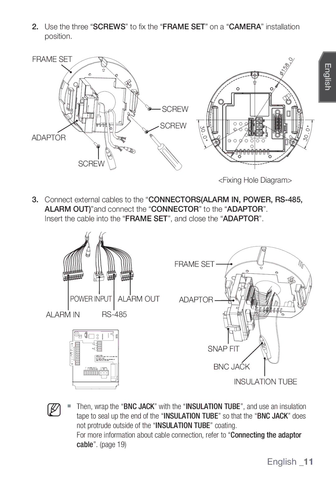
Overview
English
Overview
FCC Statement
Important Safety Instructions
Contents
WHAT’S Included
Features
Frame SET
Alarm Power Input Alarm OUT
AT a Glance
Camera
Installation
Installation & connection
Preparing Installation
Snap FIT BNC Jack Insulation Tube
Alarm
Frame SET
Screw Adaptor
Camera Frame SET Rack Hook Protective Tape
Bracket Wire Frame SET 22P Connector
Button Cover
Button Frame SET Cover Camera
Samsung Half Samsung Full
Initial Setup
Camera Address Setup
Communication Protocol Setup
Factory default is 9600 BPS
Baud Rate Setup
Setting RS-422A/RS-485 Termination
Use pins #5, #6 of SW603 to set the baud rate
SW1-ON
CONTROLLER/DVR Power Source
Connecting with Other Device
Connecting to a monitor
Monitor Alarm Alarm OUT
To connect the controller
To connect Alarm
To connect Alarm OUT
Adaptor Board
Connecting the adaptor cable
Power Supply
Using OSD icons
Setup
HOW to USE the Keyboard Controller
Duration
Main Menu
Level
Profile
ITS
Gaming
EXT Burst
DAY Mode
Night
Burst
Location Specify the display position of the camera ID
You can configure the general settings of the camera module
Camera SET
Camera ID
AGC
Iris
SENS-UP
Motion
DNR
Shutter
DAY/NIGHT
Flickerless
XDR
Setup
White BAL
Mode AWC RED Blue
Display P/T
Focus Mode
Zoom Speed
Display Zoom
POSI/NEGA
Sync
AGC Color SUP
Reverse
Mask Area
You can enable the motion detection and tracking functions
Intelligent Video
Advanced
Display
Resolution
Alarm OUT
Privacy Zone
Preset
Set Preset ID to on and enter
Select the preset number
Select Position and adjust PAN
TILT/ZOOM to the desired setup using Joystick
Select Main MENU-AUTO SET
Auto Pan Setup
Auto SET
You can set the Auto PAN, PATTERN, and Auto Play
Nish Auto PAN setup
Select the Start and move the camera using pan/tilt/zoom
Pattern Setup
Scan Setup
Auto Play Setup
Select Main MENU-ZONE SET
Zone SET
You can set the north direction and the zone coverage
Select Main MENU-ALARM SET
Alarm SET
Auto SET Sets the pattern and scan
Other SET
Clock SET
Proportional P/T
Factory Defaults
Password
OSD Color
Select Main MENU-SYSTEM Info
Communication
System Info
You can check the system information
You can set the language of the user interface
Language
Function Key
Appendix
Shortcut Keys
INT/LINE Lock
Specifications
Smart Dome Camera
Tilt
PAN
Product Appearance
Page
Caméra Smart Dome
Avertissement
Présentation
Français
Présentation
Français
Instructions Importantes Relatives À LA Sécurité
Présentation
Contenu
Contenu DE L’EMBALLAGE
Caractéristiques
Armature
Alarm Entrée DE L’ Alimentation Alarm OUT
Aperçu
Caméra
« Armature » Adaptateur BOUTON-PRESSION Câbles
Installation et branchement
Préparation DE L’INSTALLATION
Gabarit Plafond Câbles Plafond Gabarit Câbles
BOUTON-PRESSION Prise BNC Tube D’ISOLATION
Diagramme des trous de fi xation
Armature Entrée DE L’ Alimentation Alarm OUT Adaptateur
Armature VIS Adaptateur
Ruban DE Protection
Support DE FIL Armature Connecteur 22P
Caméra Armature
Support Caméra Crochet
Bouton Boîtier
Bouton Armature Boîtier Caméra
Samsung Moitié Samsung Plein
Configuration Initiale
Configuration de l’adresse de la caméra
Configuration du protocole de communication
Agencement semi-duplex RS485
Configuration du débit de transmission
Réglage DE LA Terminaison RS-422A/RS-485
La valeur par défaut définie à l’usine est 9600 BPS
Agencement duplex RS-422A/RS-485
Borne vidéo à larrièredu moniteur Câble BNC
Branchement À UN Autre Dispositif
Branchement à un moniteur
Pour brancher la commande
Pour brancher une Alarm
Pour brancher une Alarm OUT
Tableau de l’adaptateur de la caméra
Branchement du câble d’adaptateur
Alimentation
Quitter Pour quitter le menu de confi guration
Configuration
Comment Utiliser LA Commande À Clavier
Signification des icônes OSD
Predefini
Menu Principal
Profil
Niveau
Profil
JEU
Rouge Bleu
Jour Mode
Nuit
EXT
ID DE Camera
REG Camera
Cjour Si Retroecl est réglé à
Dans la caméra
Niveau Sélectionnez un niveau de
Luminance global
Augmenter Sens
Mouve
Obturateur
JOUR/NUIT
ANTI-BATTEMENT
Configuration
BAL Blancs
Bleu Gain R
Affichage P/T
Mode Focus
Vitesse Zoom
Affichage Zoom
SIN Stabilisation d’image numérique
AGC SUP Couleur
Inverse
Zone Masquage
Vidéo Intelligente
Avance
Sensibilite
Sort Alarme
Zone Privee
Affichage
Sélectionnez Menu Principal
Predefinir
Prédéfi ni
Regl Auto
Configuration de Pan Auto
Sélectionnez chaque article et réglez en conséquence
Sélectionnez Menu Principal Regl Auto
Configuration de Balayage
Rég Ronde
Auto
Configuration de Lecture Auto
Sélectionnez le numéro associé à
’écran Lecture Auto apparaît
Réglez REG Zones à on
REG Zone
Réglez Azimuth à on
Sélectionnez Menu Principal Regl Alarme
Regl Alarme
Ctrl Sortie AUX SORTIE1
Sélectionnez Menu Principal REG Horloge
REG Horloge
Autre REG
Vitesse
Reinit Reglage Usine
Coulr OSD
Proport
’information actuelle sur le système s’ affi che
Info Systeme
Communication
Vous pouvez vérifier l’information sur le système
Vous pouvez régler la langue de l’interface utilisateur
Langue
Fonction Touche
Alarme
Annexe
Touches DE Raccourci
Système Couleur Standard Ntsc
Caractéristiques Techniques
Caméra Smart Dome
Orientation
Article Description Plage de panoramique 360˚ sans fin
Vitesse de panoramique manuel 0,01˚ à 180˚/sec
Plage d’orientation -6˚ à 186˚
Apparence DU Produit
Page
Cámara Domo Inteligente
Advertencia
Descripción general
Español
Precaución
Aviso de Conformidade com a IC
Declaración DE FCC
Instrucciones DE Seguridad Importantes
Índice
Componentes
Características
Cuadro DE Ajustes
Alarm Entrada Eléctrica Alarm OUT
Vista
Cámara
Plantilla Techo Cables Techo Plantilla Cables
Instalación y conexión
Preparación DE LA Instalación
Instalación
Cierre a Presión Terminal BNC Tubo Aislante
Diagrama de orifi cios de sujeción
Alimentación Alarm
Cuadro DE Ajustes Tornillo Adaptador
Cámara Cierre Enganche Cinta Protectora Película Protectora
Cable DEL Soporte Cuadro DE Ajustes Conector 22P
Cámara Cuadro DE Ajustes
Tope DE
Botón Cubierta
Botón
Cámara
Cubierta
Medio Samsung Samsung Completo
Configuración Inicial
Configuración de la dirección de la cámara
Configuración del protocolo de comunicaciones
El ajuste por omisión de fábrica es 9600 BPS
Configuración de la velocidad en baudios
Configuración de la terminación RS-422A/RS-485
Terminación
Conexión a un monitor
Monitor CONTROLADOR/DVR ENTR. Alarma
SAL. Alarma Fuente DE
Conexión a Otro Dispositivo
Para conectar el controlador
Para conectar Alarm
Para conectar Alarm OUT
Tarjeta del adaptador
Conexión del cable del adaptador
Alimentación eléctrica
Utilización de los iconos de OSD
Configuración
USO DEL Controlador DEL Teclado
Perfil
Menú Principal
Nivel
Perfil
Estand ITS
ROJ Azul
Noche
Cont EXT
DIA Modo
ID Camara
AJ Camara
Si AMP Sens se define en no o en
Con esto, puede ajustar el nivel de AGC de
Una cámara
Sensibilidad
AMP Sens
MOV
OBT
Puede especificar un modo de grabación según la escena
SIN Parp
DÍA/NOCHE
Configuración
BAL. BL
Seleccione AJ Camara BAL. BL
Exhibir P/T
Modo Foco
VEL. Zoom
Exhibir Zoom
Es posible que DIS no funcione en las siguientes imágenes
Retro
DIS Estabilizador digital de imágenes
Area Masc
Video Inteligente
Avanzado
RES
Zona Priv
Pant
Sens
Con el joystick, defi na el tamaño de la
Preaj
De TAM. y Ubic
Seleccione el TAM y presione Enter
Defi na ID Preaj en SÍ e introduzca el nombre
Seleccione el número de preajuste
PAN AUT
Configuración automática de panorámica
AJ AUT
Seleccione cada elemento y defínalo de la forma apropiada
Patrón
Configuración de patrón
Configuración de barrido
Configuración de reproducción automática
AJ ID Zona
AJ Zona
Seleccione Menu PRI.- AJ Alrm
Mientras se genera una alarma, no se detecta movimiento
AJ Alrm
SAL1 SAL2 SAL3
Define si mostrar el reloj en pantalla y su formato de hora
AJ. Reloj
Otro AJ
VEL. P/T
ESTAND. Fabrica
Color OSD
Prop
Puede comprobar la información del sistema
COM
INF. Sist
Puede seleccionar el idioma de la interfaz del usuario
Idioma
Función Tecla
Apéndice
Teclas DE Acceso Directo
Sistema DE Color Estándar Ntsc
Especificaciones
Inclinación
Aspecto DEL Producto
Page
スマート・ドーム・カメラ
感電の危険がありますので開 けないで下さい
機器を湿度や埃、すすのある場所に設置しないで下さい。 火災や感電の原因に なり ます。
日本語
メインプラグは切断装置として使用され、いつでも利用可能になります。
IC遵守のお知らせ
FCC声明
本装置が有害な電波妨害を引き起こさないこと。
14. 全ての修理は資格のあるサービス・スタッフに任せて下さい。
重要な安全ガイド
ラジエーター、熱レジスタ、あるいは熱を発するその他の装置(アンプを含 む)などの熱源の傍に設置しないで下さい。
11. メーカーが指定する付属品のみを使用してください。 12. カート、スタンド、三脚、ブラケットはメーカー指定のも
取付け
重要な安全ガイド
キット内容
設置の準備
高速精密制御を実現するPAN/TILT
キット内容
電源入力
カメラ
フレームセット
フック レンズ
アダプタのスナップフィットを押してアダプタを開き、ケーブルが フレームセット から出るようにします。 外部ケーブル
設置の準備
取付け
この型板は、天井のほこりがカメラ部分に入ることを防ぎます。 ケーブル
BNCジャック
電源入力 Alarm OUT
Alarm in RS-485
スナップフィット
保護テープ
ブラケットワイヤ フレームセット 22Pコネクタ
カメラ フレームセット ラック
カメラ ラック フック
ボタン カバー
通信プロトコルの設定
初期設定
カメラアドレスの設定
工場出荷時の設定は9600 BPSです。
ボーレートの設定
RS-422A/RS-485ターミネーションの設定
SW603のピン番号5と6を使用して、ボーレートを設定します。
RS-422A/RS-485 全二重構造
BNC ケーブル
他のデバイスとの接続
モニターへの接続
モニター アラーム入力 アラーム出力
信号線の片端を、接地しているGNDポートに接続します。
Alarm INの接続
Alarm OUTの接続
コントローラの接続
アダプタをカメラの電源端子に接続します。 アダプタの電源コードを電源コンセントに差し込みます。
アダプタケーブルの接続
アダプタボード
このアイコンは、サブメニュー項目を含むメニューの右側に表示されます。
キーボードコントローラの使用方法
OSDアイコンの使用
設定を保存すると、終了時に変更無効を選択しても、変更 はそのまま残ります。
メインメニュー
プロフィール
モード
XDR Medium
ナイト
バースト
カメラID
カメラ設定
ユーザー サブメニューを選択した状態で
アイリス
ALC 絞りの開閉を調整します。
AGCのレベルを指定して、カメラモーションを制御できます。
モーション
シャッター
感度アップ
デイ/ナイト
フリッカレス
自動モードで赤外線光源を使用すると、自動切替えやオート フォーカスの誤動作が 発生する可能性があります。
ナイト¨デイの持続時間 フィルタ切替を決定するために必要な時間。
ATW1 2,500K ~ 9,300K Ú1 ATW2 2,000K ~ 10,000K
ホワイトバランス
照明は一般に、色温度と呼ばれ、ケルビン(K)単位で表されます。 通常照 明の色温度は次のとおりです。
ATW1,2 ホワイトバランスメ ニューをATW1またはATW2
赤の強さを調整します。 青の強さを調整します。
ナイトモードをオフに設定すると、
該当する項目でENTERを押すと、ATWがただちに実行されます。 Rゲイン/Bゲインの値を設定できます。
ディスプレー
フォーカスモード
ズーム速度
ズーム ディスプレー
デジタル手ブレ補正
垂直同期
マスクエリア
インテリジェントビデオ
アドバンスド
ゾーン設定
プライバシーゾーン
ディスプレイ
アラーム出力
メインメニュー-プリセットを選択
プリセット
ピクセルレベルを選択します。
サイズを選択してENTERを押します。 ジョイスティックを使用して、プライバ シーゾーンのサイズを設定します。
36 設定
オートパン設定
オートセット
各項目を選択し、設定します。
38 設定
スキャン設定
スキャンもしくはオートパンは1~4、 パターンは1~3、プリセットは0~511 の範囲で設定できます。
オートプレイ設定
方位をオンに設定します。
領域設定
北の方角と領域範囲を設定できます。
メインメニュー-領域設定を選択し ます。
メインメニュー-アラーム設定を選 択します。
アラーム設定
ラーム入力に対応する動作をスキャン
メインメニュー-時間設定を選択し ます。 ディスプレイを選択し、画面上に時刻 を表示するかどうかを設定します。
時間設定
その他設定
画面上に時計を表示するかどうか、および時刻フォーマットを設定します。
自動調整
工場初期値
カラー
プロポーショナル P/T
システム情報を確認できます。
システム情報
カメラのRS-485通信を設定できます。
メインメニュー-通信を選択します。 各項目を選択、設定します。
メインメニュー-言語を選択します。 下キーを使用して、言語を選択しま す。
ユーザー・インタフェースの言語を設定できます。
48 付録
ショートカットキー
有効画素数
製品タイプ スマート・ドーム・カメラ
消費電力
NTSC標準カラーシステム 画像センサー
チルト プリセット・チルト速度 最大600度/秒 手動チルト速度 0.01~180度/秒 リモコン
パン範囲 360度エンドレス
プリセットパン速度 最大600度/秒
手動パン速度 0.01~180度/秒
製品外観
Page
Câmera Smart Dome
Aviso
Visão geral
Português
Atenção
Declaração FCC
Instruções DE Segurança Importantes
Aj Câmera
Recursos
Que está Incluso
Teclado
QUE Está Incluso
Recursos
Unidade DA Base
Alarm Entrada DE Alimentação Alarm OUT
Informações Resumidas
Câmera
Instalação
Instalação e conexão
Preparando a Instalação
Insira o cabo na Unidade DA Base e feche o Adaptador
Diagrama de fi xação de parafuso
Unidade DA Base Entrada DE Alimentação Alarm OUT Adaptador
Unidade DA Base Parafuso Adaptador
Câmera Unidade DA Base Raque Gancho Fita Protetora
Cabo DA Braçadeira Unidade DA Base Conector 22P
Botão Tampa
Botão
Câmera Tampa
Parte inferior do suporte da câmera
Configuração Inicial
Configuração do endereço da câmera
Configuração do protocolo de comunicação
Padrão de fábrica é de 9600 BPS
Configuração da taxa de transmissão
Configuração da terminação RS-422A/RS-485
Terminação
Cabo BNC
Conectando a Outro Dispositivo
Conectando a um monitor
Para conectar o controlador
Para conectar a Alarm
Para conectar a Alarm OUT
Placa do adaptador
Conectando o cabo do adaptador
Fonte de alimentação
Sair Sai da tela de confi guração do menu
Configuração
Como Utilizar O Controlador do Teclado
Utilizando os ícones de OSD
Posição PRÉ-AJ
AJ Câmera Você pode confi gurar a câmera Inteligência
Nível
Padrão
LUZ Fundo
Jogo
VER Azul
Noite
Cont
EXT Cont
LOCAL. Especifi que a posição de exibição do ID da câmera
Você pode fazer as configurações gerais do módulo da câmera
AJ Câmera
ID Câmera
Automaticamente a sensibilidade
Se AM Sens estiver configurada para
Uma câmera Com o AGC ativo, se a intensidade do sinal
Sinal de vídeo para melhorar
AM Sens
DIA/NOITE
SEM Trem
Você pode especificar Másc 1 e 2 simultaneamente
ATW1 2500K ~ 9300K Ú1 ATW2 2000K ~ 10000K
BAL. BR
Ambiente
Operação de expansão/inclinação/zoom
Exibir Zoom
Exibir P/T
Foco automático. Se você ajustar o foco
DIS pode não funcionar corretamente nas seguintes imagens
SUP COR AGC
DIS Estabilização de imagem digital
Nas situações a seguir, as funções de
Vídeo Inteligente
Avançado
Área Másc
Saída ALM
Configuração da zona
Configure a sensibilidade do sensor de movimento
PRÉ-AJ
Selecione o número predefi nido
Selecione Menu PRI AJS Auto
Configuração de expansão automática
Você pode configurar PAN AUTO, Rotina e Repr Auto
AJS Auto
Selecione cada item e confi gure conforme apropriado
Números de Varredura configurados
Configuração de rotina
Configuração da varredura
Tela de confi guração de Repr Auto é
Configuração de reprodução automática
Selecione Repr Auto e depois um
Número
Confi gure Azimute para LIG
Você pode configurar a direção norte e a cobertura da zona
Selecione Menu PRI AJ Zona
Selecione Menu PRI AJ ALM
AJ ALM
Associadas às entradas de alarme de
De varredura para a entrada de alarme
Quando o alarme é gerado, a câmera
Associada ao alarme correspondente
Outro AJS
AJ Relóg
REC Auto Calibração Automática
Padrões Fábrica
COR OSD
Veloc
Você pode verificar as informações do sistema
Comun
Você pode configurar o idioma da interface do usuário
Função Tecla
Apêndice
Teclas DE Atalho
INT/BLOQ Linh
Especificações
Câmera Smart Dome
Faixa de inclinação -6˚~186˚
Descrição Faixa de PAN 360˚sem fim
Velocidade de expansão predefinida 600˚/s, máximo
Velocidade de expansão manual 0,01˚~ 180˚/s
Apresentação do Produto
AB68-00890A
 SCREW
SCREW