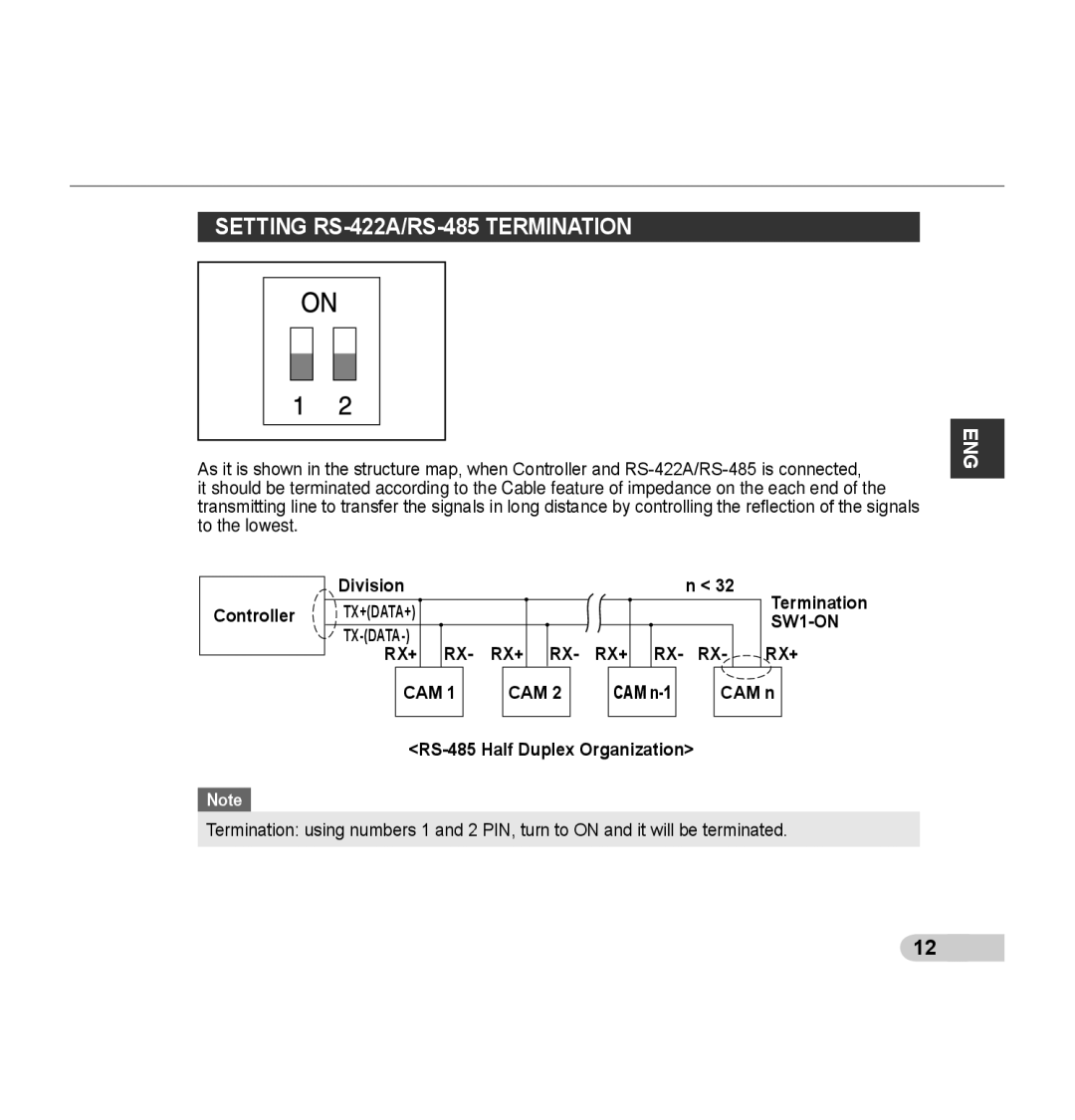
SETTING RS-422A/RS-485 TERMINATION
As it is shown in the structure map, when Controller and
it should be terminated according to the Cable feature of impedance on the each end of the transmitting line to transfer the signals in long distance by controlling the reflection of the signals to the lowest.
ENG
Controller
Note
| Division |
|
|
|
|
|
|
|
|
|
|
| n < 32 | Termination | |||||||
|
|
|
|
|
|
|
|
|
|
|
| ||||||||||
| TX+(DATA+) |
|
|
|
|
|
|
|
|
|
|
|
|
|
|
|
|
|
| ||
|
|
|
|
|
|
|
|
|
|
|
|
|
|
|
|
|
|
|
| ||
| RX+ |
| RX- | RX+ |
| RX- | RX+ |
| RX- | RX- |
| RX+ | |||||||||
|
|
|
|
| |||||||||||||||||
|
| CAM 1 |
|
| CAM 2 |
|
|
| CAM |
|
| CAM n |
| ||||||||
|
|
|
|
|
|
|
|
|
|
|
|
|
|
|
|
|
|
|
|
|
|
Termination: using numbers 1 and 2 PIN, turn to ON and it will be terminated.
12 ![]()
