1 CHAPTER ONE
Connecting The Set Top Box
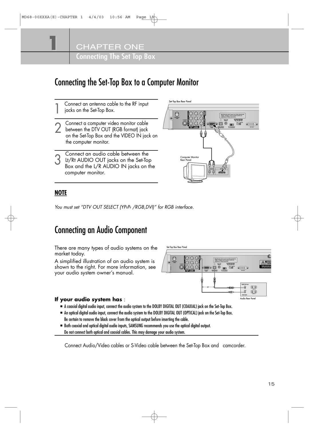
Connecting the Set-Top Box to a Computer Monitor
Connect an antenna cable to the RF input
1 jacks on the
Connect a computer video monitor cable
2 between the DTV OUT (RGB format) jack
on the
Connect an audio cable between the
3 Lt/Rt AUDIO OUT jacks on the
NOTE
You must set “DTV OUT SELECT (YPBPR /RGB,DVI)” for RGB interface.
Connecting an Audio Component
There are many types of audio systems on the market today.
A simplified illustration of an audio system is shown to the right. For more information, see your audio system owner’s manual.
If your audio system has :
A coaxial digital audio input, connect the audio system to the DOLBY DIGITAL OUT (COAXIAL) jack on the
An optical digital audio input, connect the audio system to the DOLBY DIGITAL OUT (OPTICAL) jack on the
Be certain to remove the black cover from the optical output before inserting the cable.
Both coaxial and optical digital audio inputs, SAMSUNG recommends you use the optical digital output.
Do not connect both optical and coaxial cables. This may damage your audio system.
Connect Audio/Video cables or
15