2 |
NAMES AND FUNCTIONS OF PARTS
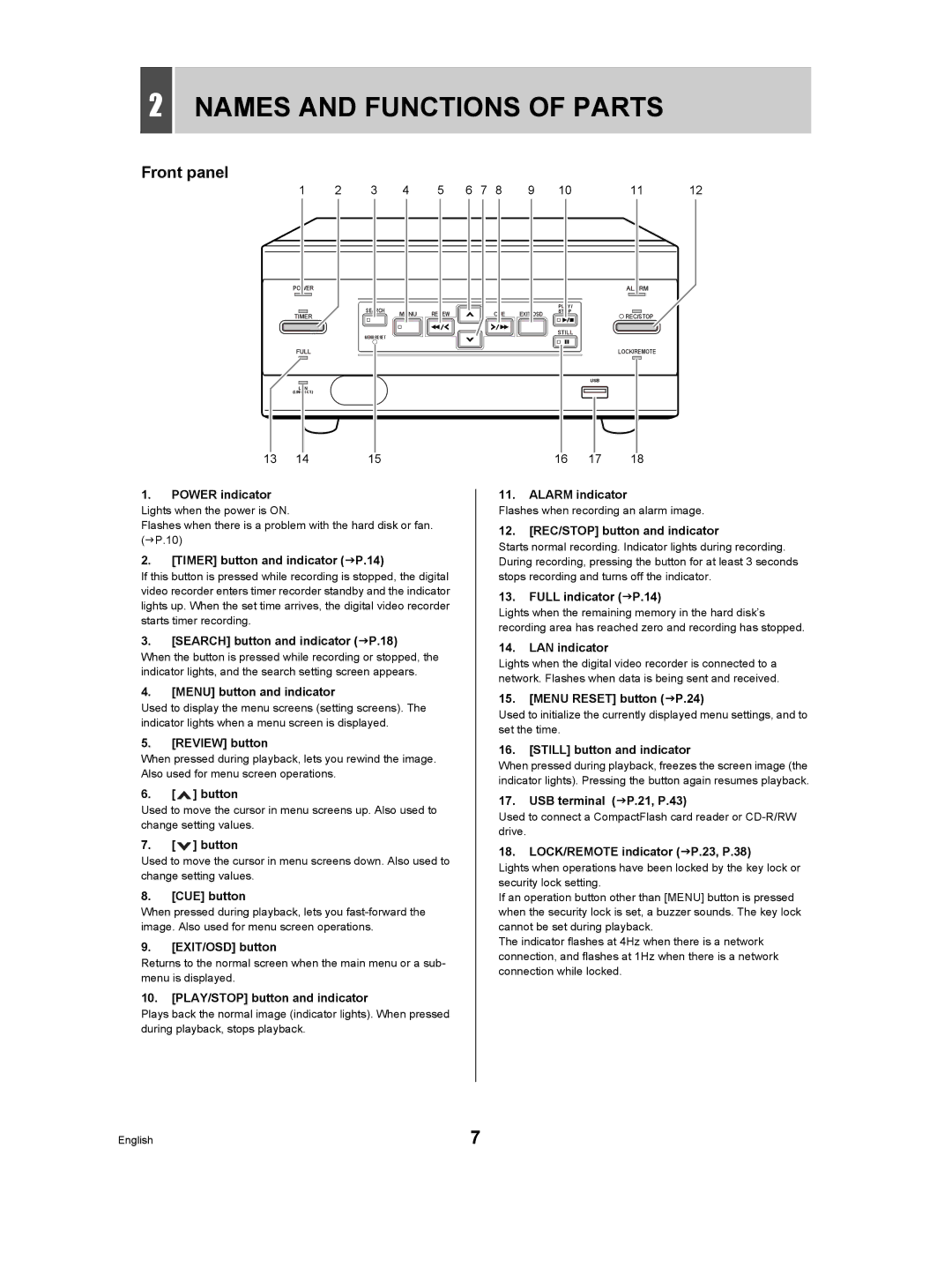
Front panel
1 | 2 | 3 | 4 | 5 | 6 | 7 | 8 | 9 | 10 | 11 | 12 |
POWER |
|
|
|
|
|
|
|
|
| ALARM |
|
|
| SEARCH |
|
|
|
|
|
| PLAY/ |
|
|
TIMER |
| MENU | REVIEW |
|
| CUE | EXIT/OSD | STOP | REC/STOP |
| |
|
|
|
|
|
| ||||||
|
|
|
|
|
|
|
|
|
| ||
|
|
|
|
|
|
|
|
| STILL |
|
|
MENU RESET
| FULL |
|
|
| LOCK/REMOTE |
|
|
|
| USB |
|
| LAN |
|
|
|
|
| (LINK/ACT.) |
|
|
|
|
13 | 14 | 15 | 16 | 17 | 18 |
1.POWER indicator
Lights when the power is ON.
Flashes when there is a problem with the hard disk or fan. (JP.10)
2.[TIMER] button and indicator (JP.14)
If this button is pressed while recording is stopped, the digital video recorder enters timer recorder standby and the indicator lights up. When the set time arrives, the digital video recorder starts timer recording.
3.[SEARCH] button and indicator (JP.18)
When the button is pressed while recording or stopped, the indicator lights, and the search setting screen appears.
4.[MENU] button and indicator
Used to display the menu screens (setting screens). The indicator lights when a menu screen is displayed.
5.[REVIEW] button
When pressed during playback, lets you rewind the image. Also used for menu screen operations.
6.[ ![]() ] button
] button
Used to move the cursor in menu screens up. Also used to change setting values.
7.[ ![]() ] button
] button
Used to move the cursor in menu screens down. Also used to change setting values.
8.[CUE] button
When pressed during playback, lets you
9.[EXIT/OSD] button
Returns to the normal screen when the main menu or a sub- menu is displayed.
10.[PLAY/STOP] button and indicator
Plays back the normal image (indicator lights). When pressed during playback, stops playback.
11.ALARM indicator
Flashes when recording an alarm image.
12.[REC/STOP] button and indicator
Starts normal recording. Indicator lights during recording. During recording, pressing the button for at least 3 seconds stops recording and turns off the indicator.
13.FULL indicator (JP.14)
Lights when the remaining memory in the hard disk’s recording area has reached zero and recording has stopped.
14.LAN indicator
Lights when the digital video recorder is connected to a network. Flashes when data is being sent and received.
15.[MENU RESET] button (JP.24)
Used to initialize the currently displayed menu settings, and to set the time.
16.[STILL] button and indicator
When pressed during playback, freezes the screen image (the indicator lights). Pressing the button again resumes playback.
17.USB terminal (JP.21, P.43)
Used to connect a CompactFlash card reader or
18.LOCK/REMOTE indicator (JP.23, P.38)
Lights when operations have been locked by the key lock or security lock setting.
If an operation button other than [MENU] button is pressed when the security lock is set, a buzzer sounds. The key lock cannot be set during playback.
The indicator flashes at 4Hz when there is a network connection, and flashes at 1Hz when there is a network connection while locked.
English | 7 |