Page
Location
Precaution
Service
Avoiding Electrical Shock and Fire
For LAN connection cable/ DVR power cord
Power cord Ferrite core
Power cord tie Application software
Introduction
Contents
Contents Settings
Other
Before USE
Installation conditions
Hard disk and cooling fan are consumables
Hard disk protection
Backup battery
For important recordings
Care
Names and Functions of Parts
Front panel
Rear panel
Power cord holder
ALL Reset switch
Cord tie
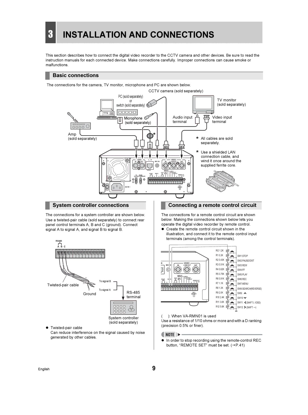
Basic connections
Installation and Connections
Connecting a remote control circuit
System controller connections
Connecting to a network
Connecting cables to the control and alarm terminals
Connecting the power cord
Changing the position of the operating display
Screen Display and Position
Operation display area
Example Normal screen
To change the language
Setting the LANGUAGE/CLOCK
When you have made a selection, press Button
Press the Menu button
Example Setting 20 May, 2004, 830 AM
Setting the LANGUAGE/CLOCK
Setting the time
Press the or button to select Press the button
Timer recording
Normal RECORDING/TIMER Recording
Normal recording
Set alarm recording
Alarm Recording
Alarm recording
When alarm input is detected
Playback
Playback while fast-forwarding/rewinding
During playback, press the Still button
Viewing still images
Frame advance reverse
Press the Still button
Searching for Recorded Images
Alarm search
Check that Alarm Search is Selected, and press the button
Image to search Search in Search screen
Date/time search
Enter the desired alarm number
You can also search by specifying the desired alarm number
Press the or button to select the image to play back
Press the button to select View Then press the button
Searching for Recorded Images
Press the button, and set the date/time to search
If no image exists for the specified time
Copying image
Preview
CD-RW
Copying to CF Cards or CD-R/RW Discs and Formatting
Formatting a CompactFlash card or
Press the and buttons to select Copy START, and then press
Setting the key lock function
Releasing the key lock function
Displaying the menu screen and sub- menu screens
Menu Configuration and Operations
To restore menu setting items to their initial values
Press the or button to select the desired menu
Overview of sub-menus
Menu Configuration and Operations
HDD SET JP.46
Select 1. LANGUAGE/CLOCK SET Press the button
Summer Time SET settings
Press the or button to change the setting
USE flashes
When USE is selected for Mode under
EXT.CLOCK SET settings
1st DVR 2nd DVR
Switch DVR DVR DVR DVR
REC Mode SET
REC Mode SET setting items
Select 2. REC Mode SET, and press Button
Settings
Starting recording again when Full indicator lights
Press the or button to select YES, then press the button
Select 3. Timer REC SET, and press Button
Timer REC SET
Timer setting items
Press the button once
Timer reservations spanning more than 24 hours
Timer REC SET
To cancel all timer reservations
Press the button to move the cursor to the next item
Setting holidays
DISPLAY/BUZZER SET setting items
DISPLAY/BUZZER SET
Select 4. DISPLAY/BUZZER SET, Press the button
Press the and buttons to change the setting, then press
DISPLAY/BUZZER SET screen appears
Setting passwords
Password setting example
Password setting
Security Lock SET
Setting the user password
Security Lock SET
Cursor to REC Control
Admin or User
Press the and buttons to move
Lights, and the security lock is set
RS-485/NETWORK SET
Network connections and settings
Settings for PC or network connection
Select 6.RS-485/NETWORK/REMOTE SET and press the button
RS-485 connections and settings
Select 6. RS-485/NETWORK/REMOTE SET, and press the button
Setting Remote SET
Disable flashes
Select 7. Power LOSS/USED Time Press the button
Power LOSS/USED Time
Displays the total amount of disk 1 operation time
Select 8. Menu Upload DOWNLOAD, and press the button
Menu UPLOAD/DOWNLOAD
Operations
Menu button Button button
To save menu items to CompactFlash card
„ If Mirroring setting is loaded
Press the and buttons to select YES and press the button
No flashes
Formatting CompactFlash cards
To exit
Initializing the hard disk
HDD SET
Select 9. HDD SET, and press Button
Hard disk setting screen
Setting conditions
Adding a hard disk
RS-485 specifications
RS-485 termination switch settings
DVR/VCR command table
Specifications
PAL
Dimensions
Unit mm 210 Front 391.5 Side
Index
TV System selector switch UP button
Timer button Timer indicator
Timer recording
Index

 terminal