DWM-2500 specifications
The Sanyo DWM-2500 is a versatile and portable dual-screen mobile TV that was crafted to cater to the growing demand for on-the-go entertainment. Known for its compact design, this model was particularly appealing to consumers seeking a portable yet functional device that could bring television viewing to a variety of settings, whether at home, during travel, or while enjoying outdoor activities.One of the standout features of the Sanyo DWM-2500 is its dual-screen capability, which allows users to watch two channels simultaneously. This innovative design is particularly beneficial for families or groups who may have differing viewing preferences, as it enables multiple users to enjoy varied content without interruption. Each screen boasts a sharp and vibrant display, ensuring that both visual clarity and color depth enhance the viewing experience.
The DWM-2500 incorporates cutting-edge technologies that elevate its user experience. It utilizes a digital tuner that guarantees reception of over-the-air broadcasts, including free digital channels. This feature not only broadens the range of content available to users but also ensures that the signal strength and picture quality remain high, even in less-than-ideal reception areas.
Battery life is another critical consideration for mobile devices, and the Sanyo DWM-2500 does not disappoint. It comes equipped with a built-in rechargeable battery, offering several hours of continuous use, making it suitable for long trips or outdoor use without the need for constant recharging. The device also includes various power-saving modes to extend battery life even further.
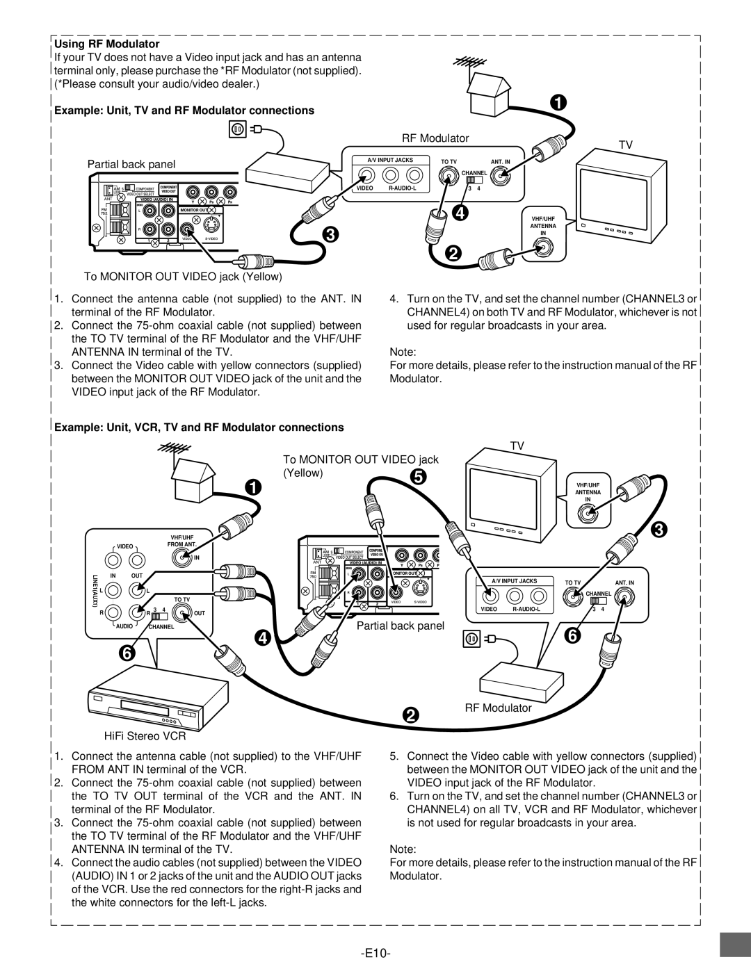
In terms of connectivity, the DWM-2500 is designed to be user-friendly and versatile. It features multiple input options, including HDMI and USB ports, allowing users to connect additional devices such as gaming consoles, DVD players, or flash drives loaded with media. This connectivity ensures that the DWM-2500 can serve not only as a TV but as a multifunctional entertainment hub.
The Sanyo DWM-2500 exemplifies the blend of convenience and performance in modern portable television technology, making it an attractive option for those who prioritize flexibility and quality in their viewing experience. With its dual-screen functionality, digital tuning capabilities, long battery life, and varied connectivity options, the DWM-2500 stands out as a noteworthy device in the realm of mobile entertainment.

