Antenna Connections
CAUTION:
When installing an outdoor antenna, follow the installation instructions in the attached “IMPORTANT SAFETY INSTRUCTIONS”.
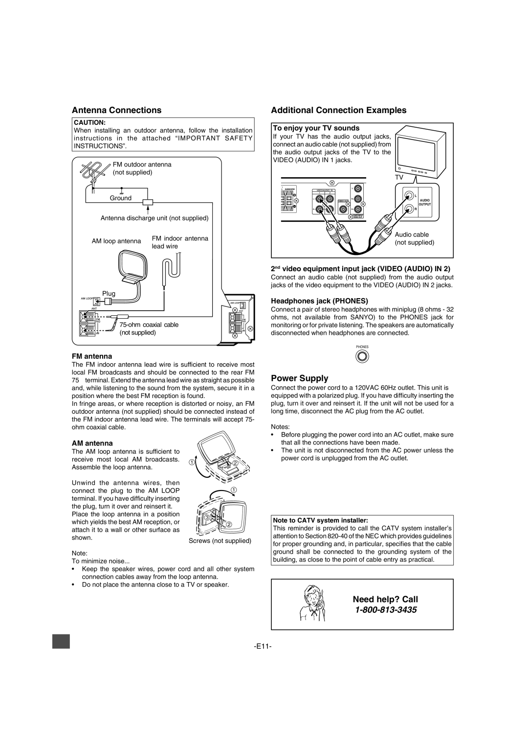
FM outdoor antenna (not supplied)
Ground
Antenna discharge unit (not supplied)
AM loop antenna | FM indoor antenna | |
lead wire | ||
|
Additional Connection Examples
To enjoy your TV sounds
If your TV has the audio output jacks, connect an audio cable (not supplied) from the audio output jacks of the TV to the VIDEO (AUDIO) IN 1 jacks.
TV
L
AUDIO
OUTPUT
R
Audio cable (not supplied)
Plug
FM antenna
The FM indoor antenna lead wire is sufficient to receive most local FM broadcasts and should be connected to the rear FM 75Ω terminal. Extend the antenna lead wire as straight as possible and, while listening to the sound from the system, secure it in a position where the best FM reception is found.
In fringe areas, or where reception is distorted or noisy, an FM outdoor antenna (not supplied) should be connected instead of the FM indoor antenna lead wire. The terminals will accept 75- ohm coaxial cable.
2nd video equipment input jack (VIDEO (AUDIO) IN 2)
Connect an audio cable (not supplied) from the audio output jacks of the video equipment to the VIDEO (AUDIO) IN 2 jacks.
Headphones jack (PHONES)
Connect a pair of stereo headphones with miniplug (8 ohms - 32 ohms, not available from SANYO) to the PHONES jack for monitoring or for private listening. The speakers are automatically disconnected when headphones are connected.
PHONES
Power Supply
Connect the power cord to a 120VAC 60Hz outlet. This unit is equipped with a polarized plug. If you have difficulty inserting the plug, turn it over and reinsert it. If the unit will not be used for a long time, disconnect the AC plug from the AC outlet.
Notes:
AM antenna
The AM loop antenna is sufficient to receive most local AM broadcasts. Assemble the loop antenna.
Unwind the antenna wires, then connect the plug to the AM LOOP terminal. If you have difficulty inserting the plug, turn it over and reinsert it.
Place the loop antenna in a position which yields the best AM reception, or attach it to a wall or other surface as shown.
1![]() 2
2
1
3![]()
![]()
![]()
2
Screws (not supplied)
•Before plugging the power cord into an AC outlet, make sure that all the connections have been made.
•The unit is not disconnected from the AC power unless the power cord is unplugged from the AC outlet.
Note to CATV system installer:
This reminder is provided to call the CATV system installer’s attention to Section
Note:
To minimize noise...
•Keep the speaker wires, power cord and all other system connection cables away from the loop antenna.
•Do not place the antenna close to a TV or speaker.
ground shall be connected to the grounding system of the building, as close to the point of cable entry as practical.