Appendix
Configurations of Terminals
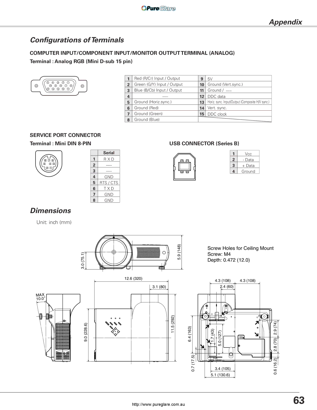
COMPUTER INPUT/COMPONENT INPUT/MONITOR OUTPUT TERMINAL (ANALOG) Terminal : Analog RGB (Mini
5 4 3 2 1
10 9 8 7 6
15 14 13 12 11
1 | Red (R/Cr) Input / Output | 9 | 5V |
2 | Green (G/Y) Input / Output | 10 | Ground (Vert.sync.) |
3 | Blue (B/Cb) Input / Output | 11 | Ground / |
4 | 12 | DDC data | |
5 | Ground (Horiz.sync.) | 13 | Horiz. sync. Input/Output (Composite H/V sync.) |
6 | Ground (Red) | 14 | Vert. sync. |
7 | Ground (Green) | 15 | DDC clock |
8 | Ground (Blue) |
|
|
SERVICE PORT CONNECTOR |
|
Terminal : Mini DIN | USB CONNECTOR (Series B) |
8 | 7 | 6 |
5 | 4 | 3 |
2 | 1 |
|
| Serial |
1 | R X D |
2 | |
3 | |
4 | GND |
5 | RTS / CTS |
6 | T X D |
7 | GND |
8 | GND |
2 | 1 |
3 | 4 |
1Vcc
2- Data
3+ Data
4Ground
Dimensions
Unit: inch (mm)
(75.1) | 5.9 (148) |
3.0 |
|
| 12.6 (320) |
| 3.1 (80) |
MAX |
|
° |
|
10.0 |
|
(228.6) | 11.5 (292) |
9.0 |
|
Screw Holes for Ceiling Mount
Screw: M4
Depth: 0.472 (12.0)
|
| 4.3 (108) | 4.3 (108) | |
|
| 2.4 (60) |
| |
6.4 (163) | 1.7 (43) | 5.0 (127) | 2.8 (70) 2.9 (74) | |
0.7 (17.5) |
| 3.4 (105) | 0.6 (16.2) | |
5.1 (130.6) | ||||
|
| |||
http://www.pureglare.com.au | 63 |