|
| Channel 2 | ||||||
Not Used |
|
|
| Channel 1 | ||||
|
|
|
|
|
|
| ||
|
|
|
|
|
|
|
|
|
|
|
|
|
|
|
|
|
|
|
|
|
|
|
|
|
|
|
15 14 13 12 11 10 9
8 7 6
5 4 3 2 1 0
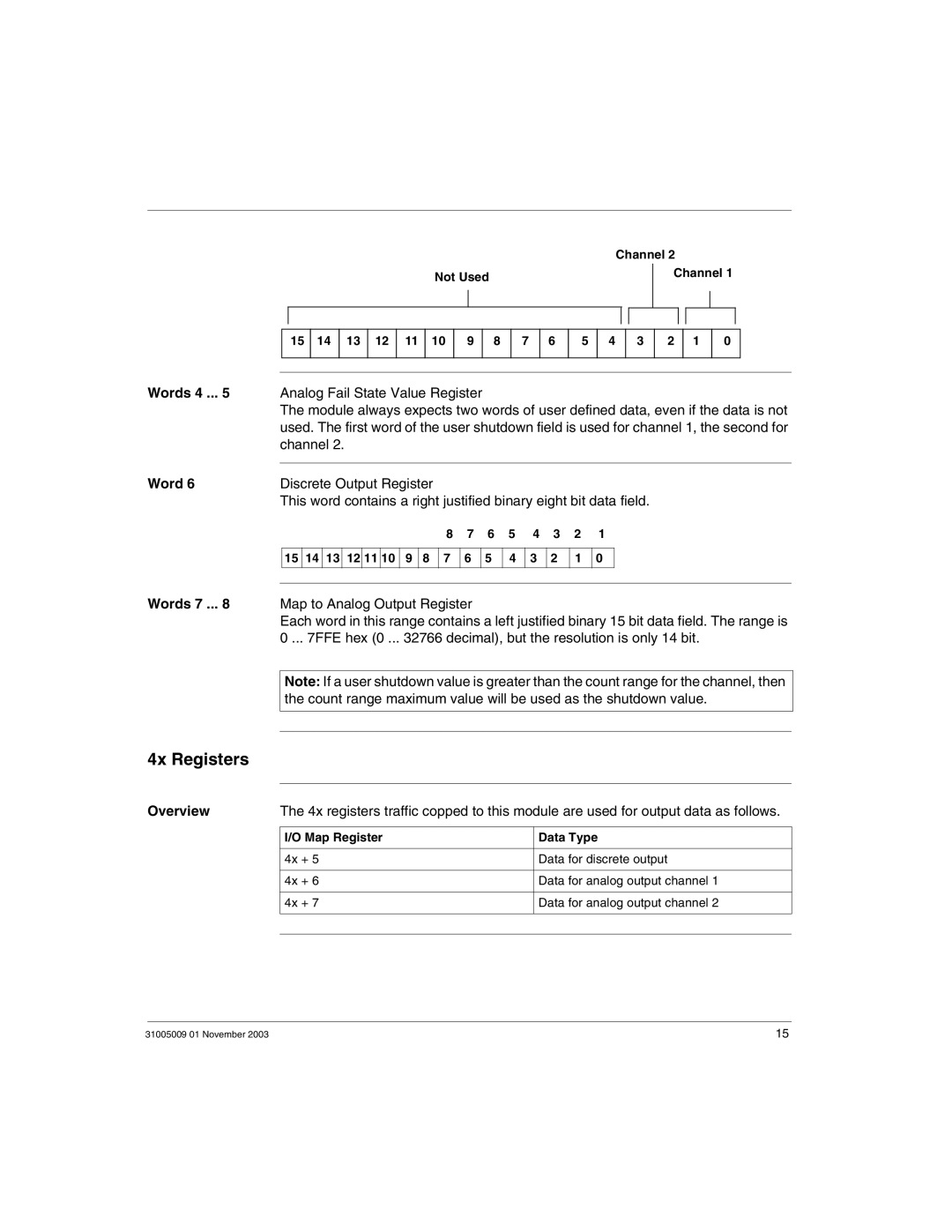
Words 4 ... 5 | Analog Fail State Value Register |
|
|
|
|
|
| |
| The module always expects two words of user defined data, even if the data is not | |||||||
| used. The first word of the user shutdown field is used for channel 1, the second for | |||||||
| channel 2. |
|
|
|
|
|
|
|
Word 6 |
|
|
|
|
|
|
|
|
Discrete Output Register |
|
|
|
|
|
|
| |
| This word contains a right justified binary eight bit data field. | |||||||
| 8 | 7 | 6 | 5 | 4 | 3 | 2 | 1 |
15 14 13 12 11 10 9 8 7 6
5 4 3 2 1 0
Words 7 ... 8 Map to Analog Output Register
Each word in this range contains a left justified binary 15 bit data field. The range is 0 ... 7FFE hex (0 ... 32766 decimal), but the resolution is only 14 bit.
Note: If a user shutdown value is greater than the count range for the channel, then the count range maximum value will be used as the shutdown value.
4x Registers
Overview | The 4x registers traffic copped to this module are used for output data as follows. | |
|
|
|
| I/O Map Register | Data Type |
|
|
|
| 4x + 5 | Data for discrete output |
|
|
|
| 4x + 6 | Data for analog output channel 1 |
|
|
|
| 4x + 7 | Data for analog output channel 2 |
|
|
|
|
|
|
31005009 01 November 2003 | 15 |
