Components of the I/O Module:
Label | Description |
|
|
1 | Internal interface (ATI) connector |
|
|
2 | Locking and ground contact for the adapter |
|
|
3 | LED status display |
|
|
4 | Protective cover |
|
|
5 | Sockets for the terminal connectors |
|
|
6 | Grounding screw |
|
|
7 | Busbar mounting slot |
|
|
8 | Locking tab for DIN rail mount |
|
|
9 | Mounting holes for panel mount |
|
|
10 | Standoff |
|
|
|
|
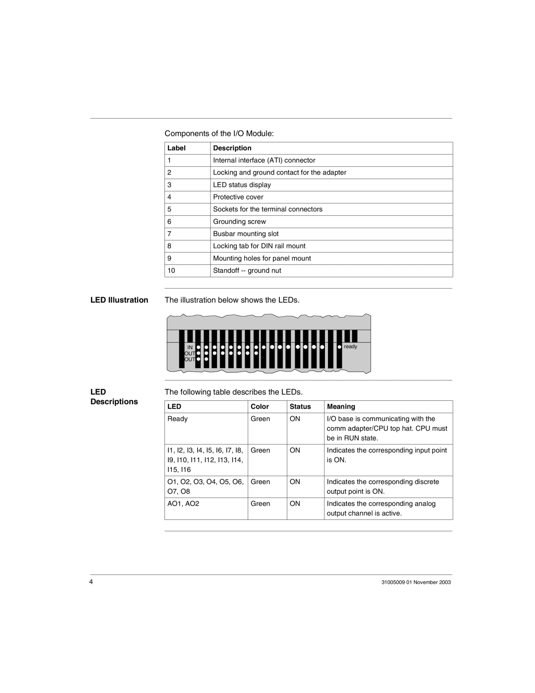
LED Illustration The illustration below shows the LEDs.
IN ![]() OUT
OUT ![]() OUT
OUT ![]()
![]() ready
ready
LED | The following table describes the LEDs. |
| |||
Descriptions |
|
|
|
| |
LED | Color | Status | Meaning | ||
| |||||
|
|
|
|
| |
| Ready | Green | ON | I/O base is communicating with the | |
|
|
|
| comm adapter/CPU top hat. CPU must | |
|
|
|
| be in RUN state. | |
|
|
|
|
| |
| I1, I2, I3, I4, I5, I6, I7, I8, | Green | ON | Indicates the corresponding input point | |
| I9, I10, I11, I12, I13, I14, |
|
| is ON. | |
| I15, I16 |
|
|
| |
|
|
|
|
| |
| O1, O2, O3, O4, O5, O6, | Green | ON | Indicates the corresponding discrete | |
| O7, O8 |
|
| output point is ON. | |
|
|
|
|
| |
| AO1, AO2 | Green | ON | Indicates the corresponding analog | |
|
|
|
| output channel is active. | |
|
|
|
|
| |
|
|
|
|
| |
4 | 31005009 01 November 2003 |