1.5 Modbus Port Models
Part Number
Mounting Method
Operating Power (Nominal)
Modbus Plus
Network
Cable
Serial Ports
Serial Protocol
NW±BM85±000 | Panel or Shelf | 115/230 Vac | Single | Modbus | ASCII or RTU |
|
|
|
|
|
|
NW±BM85C002 | Panel or Shelf | 115/230 Vac or | Single or Dual | Modbus | ASCII or RTU |
|
| 24 Vdc |
|
|
|
|
|
|
|
|
|
NW±BM85D008 | 19 in Rack | 125 Vdc or | Single or Dual | Modbus | ASCII or RTU |
|
| 24 Vdc |
|
|
|
|
|
|
|
|
|
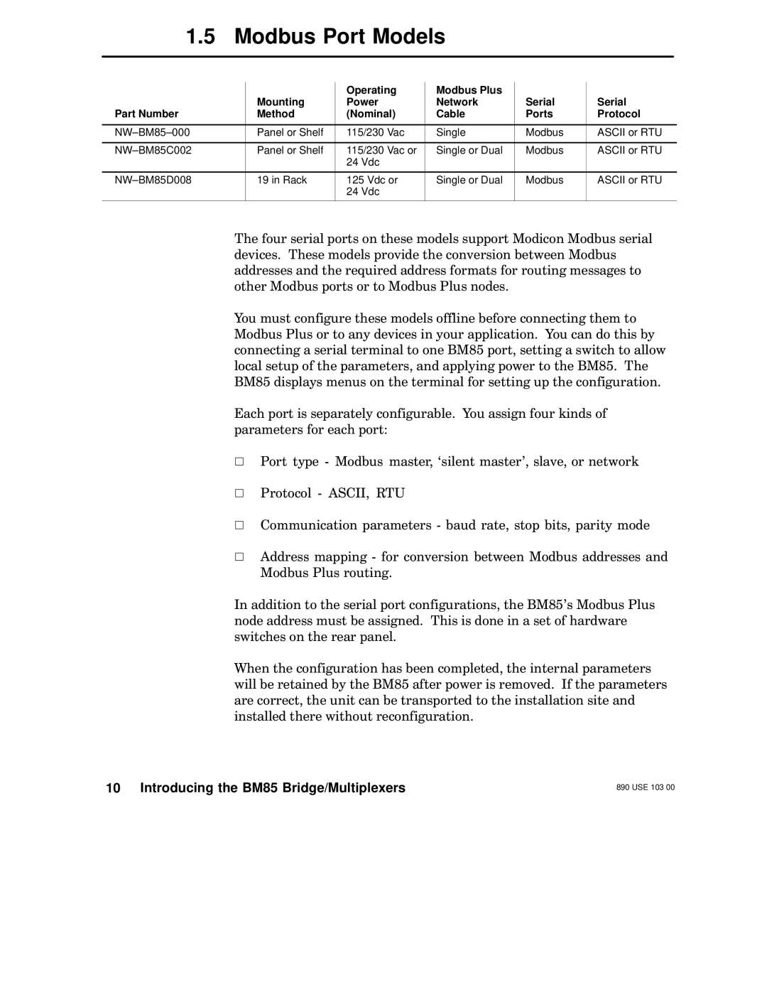
The four serial ports on these models support Modicon Modbus serial devices. These models provide the conversion between Modbus addresses and the required address formats for routing messages to other Modbus ports or to Modbus Plus nodes.
You must configure these models offline before connecting them to Modbus Plus or to any devices in your application. You can do this by connecting a serial terminal to one BM85 port, setting a switch to allow local setup of the parameters, and applying power to the BM85. The BM85 displays menus on the terminal for setting up the configuration.
Each port is separately configurable. You assign four kinds of parameters for each port:
VPort type - Modbus master, `silent master', slave, or network
VProtocol - ASCII, RTU
VCommunication parameters - baud rate, stop bits, parity mode
VAddress mapping - for conversion between Modbus addresses and Modbus Plus routing.
In addition to the serial port configurations, the BM85's Modbus Plus node address must be assigned. This is done in a set of hardware switches on the rear panel.
When the configuration has been completed, the internal parameters will be retained by the BM85 after power is removed. If the parameters are correct, the unit can be transported to the installation site and installed there without reconfiguration.
10 Introducing the BM85 Bridge/Multiplexers
890 USE 103 00
