SIMATIC S7 Ethernet
Supported Device Addresses
Overview
![]() WARNING
WARNING
UNINTENDED EQUIPMENT OPERATION
Design your system to avoid conflicting write processes between the target machine and PLC program. Values on the PLC and target machine will be incorrect if:
zThe target machine and PLC program attempt to simultaneously write to the same register.
zPLC programs or other devices write
Failure to follow these instructions can result in death, serious injury, or equipment damage.
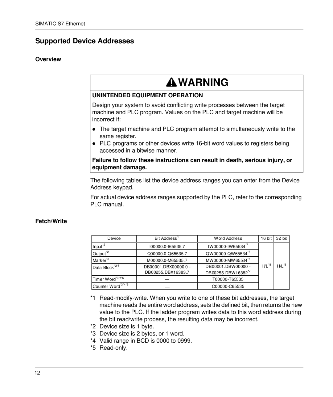
The following tables list the device address ranges you can enter from the Device Address keypad.
For actual device address ranges supported by the PLC, refer to the corresponding PLC manual.
Fetch/Write
|
| Device | Bit Address*1 | Word Address | 16 bit | 32 bit |
|
|
|
|
|
|
|
| |
| Input*2 |
|
|
| |||
| Output* 2 |
|
|
| |||
| Marker*2 | H/L*8 | H/L*8 |
| |||
| Data Block*2*6 | DB00001.DBX00000.0 - | DB00001.DBW00000 - |
| |||
|
|
| DB00255.DBX16383.7 | DB00255.DBW16382*7 |
|
|
|
| Timer Word*3*4*5 | — |
|
|
| ||
| Counter Word*3*4*5 | — |
|
|
| ||
*1 | |||||||
|
| machine reads the entire word address, sets the defined bit, then returns the new | |||||
|
| value to the PLC. If the ladder program writes data to this word address during | |||||
|
| the bit read/write process, the resulting data may be incorrect. |
|
|
| ||
*2 | Device size is 1 byte. |
|
|
|
| ||
*3 | Device size is 2 bytes, or 1 word. |
|
|
|
| ||
*4 | Valid range in BCD is 0000 to 0999. |
|
|
|
| ||
*5 |
|
|
|
|
| ||
12
